Page 1 of 2
Structured distillation column
Posted: Wed Oct 25, 2006 6:33 am
by markx
I'm tinkering on a peculiar section for my setup. Instead of a random packing (e.g. scrubbers or "structured" mesh) the column, or at least the upper section of it is stacked with SS turbines that force the rising vapour into a rapid swirl (around 600rpm). So most of the separation occurs on the inside of the column wall. It's kind of like spinning band distillation but not quite, since the turbines are stationary.
I'm trying to replicate a commercial russian setup that my friend owns. 3/4 of his 2m column is filled with these stacked turbines and he can pump up to 6kW of power through a 2" column and get good separation at 3L per hour output. The turbines leave plenty of space for the vapour so there's no danger of flooding the column.
Today I completed the first 60cm section. I'll try to add pictures soon.
Posted: Wed Oct 25, 2006 6:57 am
by markx
M'key......pictures
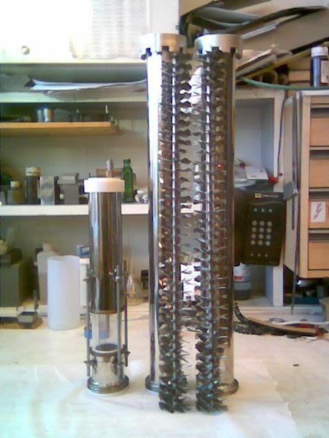
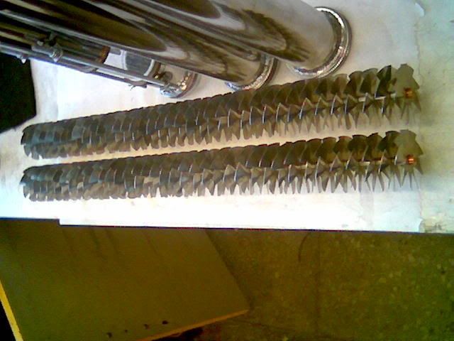
The section and the completed stack of turbines

The stack slides into the section
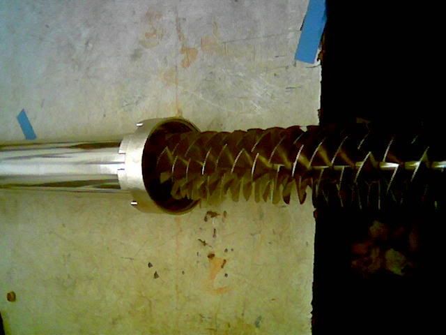
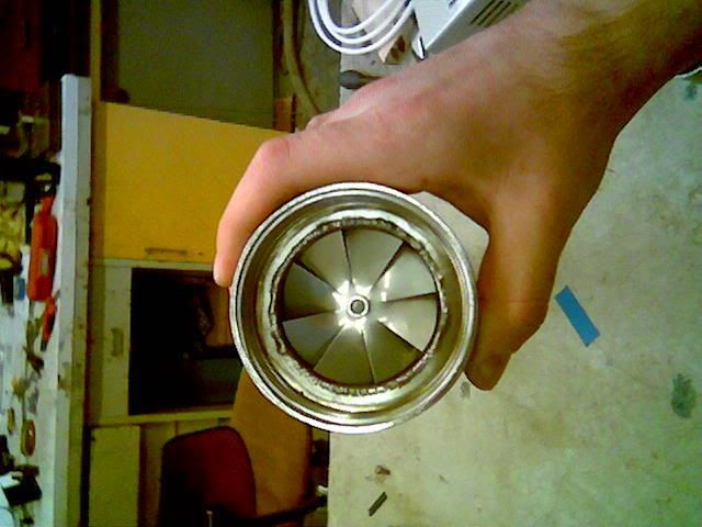
The business end of the column section
Posted: Wed Oct 25, 2006 6:58 am
by rkr
Interesting, is his output at 95.6% and can it be classified as neutral? What about the cuts?
Cheers, Riku
Posted: Wed Oct 25, 2006 7:02 am
by markx
Totally neutral azeotrope......better than the one I can achieve with IGOR. Actually he and his setup were the ones that got me into distilling in the first place

I don't know about the cuts part....so if I told I would lie, but I can ask him for more details tomorrow.
Posted: Wed Oct 25, 2006 7:43 am
by rkr
Even more interesting, few more questions. Is the column insulated? Reflux condenser on top? Is the packed part using mesh/scrubber type packing? How about those turbine wheels, each seem to have a short piece of pipe as center section. Do those sections rest on each other? When one turns does the whole stack turn?
I'd be interested in hearing the cuts and whether he carbon filters or not. Your experiences would also be appreciated.
Cheers, Riku
Posted: Wed Oct 25, 2006 9:14 am
by sherriff Buffoerd pusser
That is some nice work. Did you fab turbines? are there any type of bearings?If not will bottom tuerbine be staionary resting on column?
Posted: Wed Oct 25, 2006 10:04 am
by markx
The column of the commercial setup is fully insulated (which makes my polisihing efforts on the section at hand rather futile as is will be covered in insulation when under action) with reflux condensor head on top just like a regular setup.....except the inner beauty

The packed part (bottom of the column) uses SS mesh and as far as I can understand it's there to assure the laminar flow of the steam and cut out boiling fluctuations.
The "turbines" are stationary and do not turn, they act as the stator of a turbine would and create a helix shaped tunnel for the rising vapour....they are fixed inside the column and also fixed rigidly onto the threaded rod that holds them together. When vapour runs through them it's forced into a swirling motion. So calling them turbines is maybe a bad choice of words as it creates a false idea of how the packing operates.
The commercial setup that my friend owns has 4 sections of turbines (he only uses 3 of them as there's no more room to make the column higher). The sections are soldered and the turbine packing is also soldered into the section and is therefore unremovable (unlike mine). Maybe there is alternating turbine geometry or placement involved in the original setup since the sections are numbered and have to be arranged according to this numeration to make the setup work properly. Looking into the sections I see no difference in the turbines but maybe it lies deeper as one can only see about 10cm down the section. Well....we'll see soon enough whether my contraption works or not.
My friend uses no carbon filtering, since there's no need for that. Just a stripping run and a rectification run and he's done. I'll try to get more info on the cuts but I imagine they lie in the realm of a regular randomly packed column of comparable dimensions.
It was a real pain to fab all those little propellers...I basically cut them out by hand one by one and smoothed them on a lathe.Would be a real shame if it does not work, but I can always take the whole thing apart and alter the placement and geometry of the little suckers until it works like it should.
The interesting part is that I have found, despite all efforts, no reference to this kind of setup or column packing method on the internet nor in the online patent offices. The closest alternatives that I found were spinning band distillation and centrifugal distillation setups, both of which employ the use of rapidly spinning parts inside the column to enforce separation.
Posted: Wed Oct 25, 2006 10:09 am
by theholymackerel
Facinating.
This is totally new to me.
Thank you so much for sharin'.
Posted: Wed Oct 25, 2006 10:15 am
by rkr
It sounds a bit like the spirall still in operating principle. I.e. lots of surface area where reflux runs slowly and relatively fast moving vapor that passes these surfaces. I'd guess the important part in this setup is to have the reflux drip from one blade above to the next one below. You could probably use a long sheet of metal formed as a spiral inside the column instead of those blades. Actually I have a distant memory of reading about such setup somewhere.
Cheers, Riku
Posted: Wed Oct 25, 2006 10:18 am
by Harry
Markx said: It's kind of like spinning band distillation but not quite, since the turbines are stationary.
It's certainly an interesting concept. From a theory point of view, it allows a much longer path for the vapours to traverse the column, thus it would treble, or even quadruple the effective length of the column!
The stated ~600rpm of the vapour means it's going around the column 10 times per second. In a 2" diameter column that would be a path (length) of 6.3" per second, well within the limits for achieving good separation (12-14 ins/sec).
I just have one tiny reservation on the theory. The laws of physics will not be denied. The volume (vapour capacity) of the column doesn't change. Therefore if there's up to 6kw going in, then there's a
lot of vapour being produced. I have misgivings about whether there's enough reflux coming down to do the job, or even if the normal sized condenser could handle it!
Markx, please keep us informed of the progress (successes, failures, workarounds etc.). This could be the new
mouse-trap.
.
Posted: Wed Oct 25, 2006 11:09 am
by stillvodka
Hello,
Ive been looking at the turbine stack , I worked for this company for a number of years-
http://www.pinnaclebrush.co.uk/" onclick="window.open(this.href);return false;" rel="nofollow I don't work there any longer, but i still get on with owner,
we use to do a filter brush in stainless still, for Heat Exchangers, and they look very similar to your Turbine Stack, they were assembled by hand (That was my job) in different gauge Bristles, what ever size you wanted and whatever thickness you wanted, if you have a look at the website you will see what i mean.
Just thought it might be of interest
Regards
Posted: Wed Oct 25, 2006 11:39 am
by pothead
This is very interesting. IF it works out well, would it mean that you could get a high proof clean product with a shorter-than-average column?
Well, I supose that even in a 36" column, it would still be nice.
I would like to know more about the collection rate on a 36" column of turbines with 1500w
As for those brushes...IF those could work along the same theory, that would be pretty nice. It would be a bit less trouble to find a brush like those made of copper than it would be to make turbines of copper.
Posted: Wed Oct 25, 2006 12:59 pm
by Harry
Pothead said: IF it works out well, would it mean that you could get a high proof clean product with a shorter-than-average column?
I don't think so. I've had a bit of a think about this situation, and a few things come to mind:
The volume capacity of a given column is constant. It can't change.
That means for this design the logic is this...If you lengthen the pathway via a spiral or transverse plates, then you effectively divide the column in half down the middle, because the vapour is swirling around a central point (the lengthwise bar) of the column. Therefore a given volume of vapour is driven through a spiral pathway half the size of the column.
The amount of vapour being produced (in moles) also doesn't change (constant power input). So the vapour has to double in speed to negotiate the path and fill the available column capacity, as it's being pushed by more vapour from below.
Higher speed means less time to mingle with downward flowing reflux, therefore poorer separation. To overcome this you have to either reduce the power input to slow the vapour, or double the length of the column to allow for the expanded HETP, and compensate for the lengthwise halved column concept.
I guess there's no such thing as a free lunch.

.
Posted: Wed Oct 25, 2006 1:09 pm
by markx
There definately are no free lunches....that's tried and true but it's all theoretical speculation for now. The truth can be found only through experimentation but i've got to get this far first

Posted: Wed Oct 25, 2006 1:26 pm
by pothead
I would still like to know your progress on this. Keep us all informed.

Posted: Wed Oct 25, 2006 5:54 pm
by masonjar
Man, that looks cool. Just out of curiosity, how many times did you cut your fingers while making those turbines?
Wouldn't this design still benefit from packing between the turbines to increase the surface area?
Posted: Wed Oct 25, 2006 10:50 pm
by markx
Not once
Packing between the turbines would halt the swirling motion of the vapour and make the setup operate like a random packed column. In that case I could as well dump the propellers and pack with scrubbers instead. They would have no significant effect any how.
Posted: Thu Oct 26, 2006 5:36 am
by hornedrhodent
I wonder how this would go with an 8" SS flue pipe? It may overcome the supposed problems of getting uniformity of packing in a large dia column.
Posted: Thu Oct 26, 2006 5:45 am
by markx
You'll have to try it.....I can't see why it should not work in a 8" column, but then again I've only seen it work in 2" configuration.
Posted: Thu Oct 26, 2006 3:47 pm
by erbachem
Hiya,
I've recently been thinking about options for installing structured packing into a 6 inch duplast column. It looks like this is exactly what I have been looking for. When do you think you have your first test results available for us?
Posted: Fri Oct 27, 2006 2:18 am
by markx
I guess I'll be able to tell something about the first results in the coming week. I still have to fabricate about 10 turbines for the second section and complete the bottom section with regular packing. Plus a threaded adaptor for the reflux head, thermometer ports and some seals for the sections. I'll keep you posted on the progress.
Posted: Fri Oct 27, 2006 10:14 am
by possum
Reminds me of a cyclotron.
Neato...the proof will be in the puddin.
Posted: Sat Oct 28, 2006 5:27 am
by hornedrhodent
I'll await your 2" results before I attempt an 8" copper one.
Posted: Tue Oct 31, 2006 12:41 am
by Sinker
It's certainly an interesting concept. From a theory point of view, it allows a much longer path for the vapours to traverse the column, thus it would treble, or even quadruple the effective length of the column! Harry
It depends on the average angle of vapour flow. At 45º it travels approx 1.4 times the height (length) of the column, which is a significant extra distance. Smaller angles (to horizontal) increase both distance travelled, and vapour speed.
If you lengthen the pathway via a spiral or transverse plates, then you effectively divide the column in half down the middle, because the vapour is swirling around a central point (the lengthwise bar) of the column. Therefore a given volume of vapour is driven through a spiral pathway half the size of the column.
The amount of vapour being produced (in moles) also doesn't change (constant power input). So the vapour has to double in speed to negotiate the path and fill the available column capacity, as it's being pushed by more vapour from below.
Higher speed means less time to mingle with downward flowing reflux, therefore poorer separation. To overcome this you have to either reduce the power input to slow the vapour, or double the length of the column to allow for the expanded HETP, and compensate for the lengthwise halved column concept. Harry
I am not sure that is right, Harry. A vortex is generally radially symmetric. A fan placed inside a cylindrical tube still blows air through in a radially symmetric pattern, not just on one side, and I can't see why this impeller plate design would be different. It is not taking half the column volume and twisting it into the other half, it is twisting all the volume at once.
Take a cross-sectional slice through the column and the middle of the impeller, and add up the cross-sectional-area of the impeller. The flow through the column is somewhat restricted overall by the resistance offered by the impeller, depending mostly on the impeller blade angle, but the resistance has a radially symmetric distribution around the central point of the column.
I see three critical and interacting variables in this design concept.
1. The angle of the impeller blades. Too close to vertical and you don't get good separation. Too close to horizontal and you get too much resistance to vapour flow, and too high a vapour speed.
2. The relationship between impeller blade angle, and vertical separation between adjacent impellers.
3. The alignment of the blades of adjacent impellers (in line? offset? and by how much?).
I know about vapour speeds being considered ideal around the 10-15"/s range. But is it an absolute and fixed range? Could there be something about this impeller design concept that allows a faster vapour speed (i.e. higher output rate) without reducing output strength or purity? One possible factor is that the faster the vapour speed (up to a point), the greater the centrifugal forces acting on the vapour, and maybe this contributes to separation (ethanol and water molecules having different molar masses and densities).
I think this is a very interesting idea, with great potential. Thanks to Markx for reporting it here, and full credit to the original inventor.
Posted: Fri Nov 03, 2006 5:35 am
by markx
Progress so far:
The two sections with their jetpacks and IGOR's adapted reflux head:
I have to work on the third bottom section and then it's almost complete (the thermometer ports still have to be installed). The first test results will probably come next week.
Posted: Fri Nov 03, 2006 6:40 am
by stoker
smooth!
but I think it's just an other way of packing a column. It just creates surface in your column, the same as packing does.
hornedrhodent, is 8" copper pipe easy to find?
I'm very curious how that would look like. keep us informed!
I'll make a 4" column when I have time, college is absorbing me right now.
Posted: Fri Nov 03, 2006 7:40 am
by markx
It sure is just another way to pack your column......but with a twist
Posted: Fri Nov 03, 2006 1:22 pm
by hornedrhodent
="stoker" .
hornedrhodent, is 8" copper pipe easy to find?
Not around here - I was thinking SS flue pipe sold for wood heaters.
I could cut up some old copper hot water tanks - I have a couple which are soft soldered (probably lead based) so are unsuitable for using as boilers.
Some day - when I get a round Tuit.
Posted: Mon Nov 06, 2006 7:46 am
by markx
Third section completed........gotta take it home and put everything together so I can determine the correct placement for thermometer ports, solder them in place and that's it. In a couple days I will post the results of first test run.
Posted: Mon Nov 06, 2006 9:08 am
by pothead
How tall is this column from bottom to top(fully assembled)?