....Way back on 5/23 Hookline said a vaporlock was needed on RLM takeoff line,but I can't find any other threads to address this.
...Since I'm building 3" RLM (and not suicidal) I hope people here could show what they consider safe RLM takeoff.
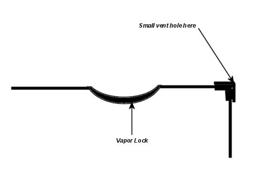
...I believe it was stated elsewhere "need small hole at high point in tubing to prevent siphoning" ,and can't see a
way to vapor lock this arrangement.
...Any help appreciated,rough sketch fine......drjulian
RLM takeoff (safety?)
Moderator: Site Moderator
Re: RLM takeoff (safety?)
You said a rough sketch was ok. 
It is the very things that we think we know, that keep us from learning what we should know.
Valved Reflux, 3"x54" Bok 'mini', 2 liebig based pots and the 'Blockhead' 60K btu propane heat
Valved Reflux, 3"x54" Bok 'mini', 2 liebig based pots and the 'Blockhead' 60K btu propane heat
Re: RLM takeoff (safety?)
I do not know if siphoning is taking place, but a small vent hole at the top of the vapour lock will make sure it does not happen.
RLM is not a fully developed design. If this is your first column it might not be the best design to start with. LM or VM are the best established designs we have.
And another version of a vapour lock is:
RLM is not a fully developed design. If this is your first column it might not be the best design to start with. LM or VM are the best established designs we have.
And another version of a vapour lock is:
Be safe.
Be discreet.
And have fun.
Be discreet.
And have fun.
Re: RLM takeoff (safety?)
Thanks Hawke,Hookline!
...Hook,it was discussion between you /Minime/others that is making me try RLM.
...Per that discussion,all I'd have to do is change valve location for LM.
...When I figure how to put sketch here,will do so.Thanks again...DrJ
...Hook,it was discussion between you /Minime/others that is making me try RLM.
...Per that discussion,all I'd have to do is change valve location for LM.
...When I figure how to put sketch here,will do so.Thanks again...DrJ
Re: RLM takeoff (safety?)
drjulian wrote:Thanks Hawke,Hookline!
...Hook,it was discussion between you /Minime/others that is making me try RLM.
So, it's all my fault, huh?
...Per that discussion,all I'd have to do is change valve location for LM.
That is the basic difference between LM and RLM. One directly controls the product output rate, one directly controls the reflux return rate.
...When I figure how to put sketch here,will do so.Thanks again...DrJ
Yes, pics and diagrams are usually a big help in discussions here.
Cheers
Hook
Be safe.
Be discreet.
And have fun.
Be discreet.
And have fun.
Re: RLM takeoff (safety?)
In this design you can swith between RLM and LM (valve on takeof required). Please be sure at least 4cm height between valve and tekeof line to increase preasure (easier reflux flow control).


Re: RLM takeoff (safety?)
cemik1,
THANKS for that drawing. Very simple, but very powerful in flexibility. I have bookmarked it for a project I plan on working over the winter.
H.
THANKS for that drawing. Very simple, but very powerful in flexibility. I have bookmarked it for a project I plan on working over the winter.
H.
Hillbilly Rebel: Unless you are one of the people on this site who are legalling distilling, keep a low profile, don't tell, don't sell.
Re: RLM takeoff (safety?)
So how does this compare to a VM or pure LM still? heads compression? looks like reflux would be very easy to control..
I cant wait to see how this goes.....
I cant wait to see how this goes.....
Re: RLM takeoff (safety?)
..Thanks again,cemik!
...The reason I like this design is..(economical)(full control of reflux)
..You have already shown how to use stock pot to continuously strip any amount of wash in one
run,so this should really do the job!
...I'm still working on my design,finished in 2 months or so,possibility of ALSO having VM control.
..I plan on using store bought liquor to test,cause fermentation may take me years to get right!
..............DrJ
RLM valve
Please remember valve in RLM is bigger than in LM. Pressure is lower (in LM the valve could be placed lower) and flow is higher (usually 4 times). It means kvn of RLM valve must be up to ten times higher than LM one. My advice is always start RLM design from valve. Calculate maximum flow (from maximum power), take 150% of it and test the valve using water. Check the height (distance between takeoff and valve) and flow. Based on the experience you can change the height (in my opinion 4cm is minimum) or valve size.
I can also include my previous post about valves:
I can also include my previous post about valves:
There are two main parameters connected with flowrate DN (nominal diameter) and Kvn (nominal flow for water, 1bar). Taken from a pdf:
DN______ Kvn
[mm]___[m3/h]
_2______0,12
_3______0,25
_4______0,45
_6______0,80
_8______1,10
There are correction formulas for other preasures and liquids. In our case only liquid level above valve is important:
Q=Kvn*sqrt(h), where h is in meters.
From the other hand 1kW power lets vapourise about 5,3 liters of ethanol per hour. In RLM system the valve must pass all the liquid. The table is now corrected and flows for 5cm and 10cm height are added:
DN______ Kvn____Kv05____Kv10
[mm]___[m3/h]___[l/h]_____[l/h]
_2______0,12_____26,8_____37,9
_3______0,25_____55,9_____79,1
_4______0,45____100,6____142,3
_6______0,80____178,9____253,0
_8______1,10____246,0____347,9
Because total amount of ethanol per kW is:
__P_____C2H5OH
[kW]_____[l/h]
__2______10,7
__4______21,3
__6______32,0
_10______53,4
we can assume that 3mm is enough but also 2 covers most cases. This is only a theory. Practical tests are strongly adviced.
Sources:
Flow correction
Valves catalogue
-
astronomical
- Rumrunner
- Posts: 683
- Joined: Fri Nov 18, 2011 4:54 pm
Re: RLM valve
Does this apply the same way with two outlets (one for product above one for reflux-both with valves)? Is this more complicated design just more work than a single outles with a T and two valves + vapor lock on reflux tube.cemik1 wrote:Please remember valve in RLM is bigger than in LM.
I dont understand how a valve can be bigger or smaller. Do you mean the outlet needs to have a larger diameter pipe, or, is there different flowrates for valves on the same size diameter pipe. I always assumed that a fully opened valve wouldn't resrict flow at all compared to a straight length of pipe. I think I'm wrong now. A little clarification would be nice.
UPDATE:
I saw your links and I see that different valves have different sized orifices. My thinking is that a RLM with only a valve on the reflux would make the valve ability much more important. If I have a valve on both the reflux and the product output than the worst case scenario would be that at my output rate I'd still be pouring off the plate even when the reflux valve is wide open. Would this really matter though? I'd imagine id still have enough flowrate through the reflux valve when it actually needed to do its job and up the RR near the end of a run.