Hi all. I have been following this site and forum for a long time and have finally decided to give it a try. It seems that no matter how much one reads, the questions keep coming, and most often the answers are here if you are willing to spend the time to find them.
I love to tinker, and therefore probably have over complicated some of this. When I have a chance and get the shop cleaned up a bit, I will take some pictures of the stuff I have made so far. It is mostly copied off of this site and slightly modified. It consists of modules which can be assembled in various ways depending on what you want to do. The modules fit together via slip fittings in the 2" main column or by 1/2" copper unions.
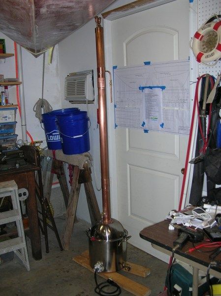
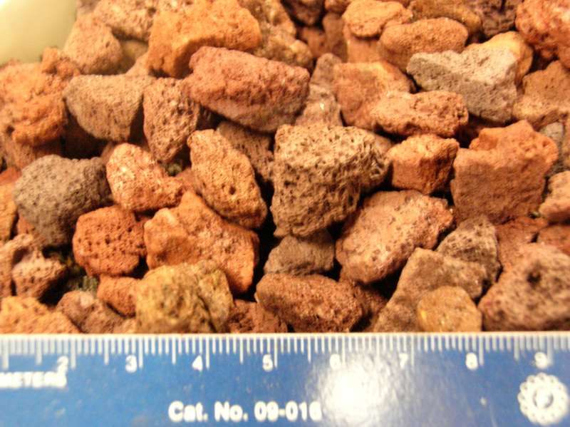
So far the modules are: a 20 L ss stock pot boiler electrically heated with a 4500 watt element and having a drainage tap compatible with garden hose; a stainless salad bowl/lid combo attached to pot with paper clips and dough gasket. It has a copper flange fitting for 2" diameter, 8" long copper column stub. There's a 3' packed column (lava rock), a boka reflux condenser and 2 cup collector. A 4' Lyne arm and 3' water jacketed condenser can be fit onto the stub in place of the reflux column to operate in pot still mode. Finally, there is a small automobile AC evaporator which operates as the condenser for a side takeoff vapor management module.
Needless to say, I will be operating in simple pot still mode for a while to get used to the process. !
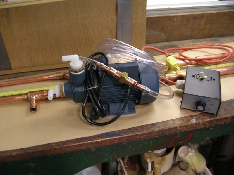
The pictures I will post will illustrate this much better than all of the words. I'm using a sturdy water pump for coolant circulation. The AC evaporator will serve to cool the coolant water. A small heater/fan combination blowing across the evaporator fins will heat or cool them. When they are heated, the circulated fluid passes through a 10' coil of 1/2" copper tubing serving as a heat source for the fermenting vat.
I'm using a StillDragon heating element controller (see question below) which utilizes a 220 volt circuit. I added a double pole single throw on - off switch to this arrangement (which cuts off both legs of the 220 volt AC line) as well as a digital AC volt/ampere meter. See question below.
The PID module is separate and operates from either 110 or 220 volts. It will incorporate a simple relay type PID to switch a low DC voltage off and on. This voltage controls a large capacity (50 A.) AC SSR which can control a number of things depending on what is being done at the time. Temperature control of the fermenting vat to name one. I had planned on incorporating a digital volt/ampere panel meter (see below).
Motor control is by a 110 volt AC power controller and SPST switch which can be used with the pump, the heater or the fan.
The electronic modules generally take the form of a small box with a pigtail and plug for power. The plug type corresponds with the voltage and power input. The output of the modules is via a receptacle with a socket pattern compatible with the power/voltage output. Generally the flow of power will be from element control(220), to PID(220 or `110), to motor control(110) with the PID taking either voltage.
Because different voltages are used in the different electronic modules, and these modules had to be joined in series at times, voltage adapter plug/socket pairs will be designed & made to safely allow this. There will not be a situation in which differing voltages are present in a module at the same time.
The current frustration involves the digital AC volt/ampere meter. It is one of those slick little cheap combo units seen on eBay. When I initially powered up the element controller, the smoke escaped from the meter about 3 minutes later and it died. The volt readout seemed to work OK for a moment and current of course didn't register anything without a load. In subsequent reading I found that the digital meters had trouble with the "chopped" output from SCR's / SSR's and the like.
The question is: what do yall most often use for AC current measurements? Those big old klunky ampere meters? Shunts? Clamp meters? Somewhere I have an old Heathkit VTVM which I suppose will work, but I'd like to have the meters incorporated into the modules if possible.
Meanwhile, I'm getting closer to the clean out run and reading about that process.
Cheers,
McTavish
Hey from Virginia
Moderator: Site Moderator
Re: Hey from Virginia
I can't even tell you how stupid the first part of your post is! I understand, IF I am understanding right, there will be no DIRECT contact with the AC EVAPORATOR? which is located under the dash(or condenser? which is the one at the front of the car) Doesn't matter they are both made with LEAD. Even INDIRECT contact is TOOOO much risk not only are you risking lead in your distillate but also in your wash!!!! Not only that but then there is the freon and besides that there is oil mixed in the freon which isn't supposed to happen but does regardless, which is what the accumulator is for. I have to say blatantly that set up is just stupidly dangerous.McTavish wrote: Finally, there is a small automobile AC evaporator which operates as the condenser for a side takeoff vapor management module.
The AC evaporator will serve to cool the coolant water. A small heater/fan combination blowing across the evaporator fins will heat or cool them. When they are heated, the circulated fluid passes through a 10' coil of 1/2" copper tubing serving as a heat source for the fermenting vat.
The current frustration involves the digital AC volt/ampere meter. It is one of those slick little cheap combo units seen on eBay. When I initially powered up the element controller, the smoke escaped from the meter about 3 minutes later and it died. The volt readout seemed to work OK for a moment and current of course didn't register anything without a load. In subsequent reading I found that the digital meters had trouble with the "chopped" output from SCR's / SSR's and the like.
The question is: what do yall most often use for AC current measurements? Those big old klunky ampere meters? Shunts? Clamp meters? Somewhere I have an old Heathkit VTVM which I suppose will work, but I'd like to have the meters incorporated into the modules if possible.
Cheers,
McTavish
It sounds as if you used the meter as part of the circuit, you shouldn't do that they are not rated to take the voltage/current like that, even cheap meters can read up to 10 amps USUALLY, I still don't understand WHY you want to see the amp draw, but a clamp meter would be your best bet.
Re: Hey from Virginia
Thanks for the comments, evilpea. Had they been based upon correct assumptions, perhaps they would have been helpful. The pictures which I will post will clarify the situation and then you can make genuinely useful comments that will at least be based on fact. Meanwhile, here's a little clarification:
- The evaporator unit is a new part - never installed - hence no freon etc. which is located wherever I need it to be. Not still in the car.
- These units are brazed, not soldered hence no worries from lead.
- The evaporator consists of only the copper tubing folded upon itself within a supporting matrix of aluminum fins. Half inch pipe unions at each end serve to attach/detach it from the coolant water or the vapor stream depending on which application it is put to. It is always part of a closed system with either vapor or cooling water within it.
It this point, I am not sure how well it will work in the vapor management mode, but you would have to see how it is set up to make any judgement on that.
I am tempted to just forget the meters. It is just nice to have some direct indication of how the power is set.
Finally, I sort of expected some sort of brash comment from someone on here. It seems there are folks out there who like to point out the errors others make and call them stupid. I think that there would be even more of the helpful criticism I see here every day if folks were just a little kinder in their remarks.
Wait for the pix, guys, then have at it, but kindly.
Cheers,
McT.

Re: Hey from Virginia
I am by know means an expert in this area but it sounds like you've done some research and I am not sure I have read much in this area so as I have told many we have some smart guys & gals on the forum but one test is worth a thousand opinions! Safety is always are first concern. Good luck looking forward to the pictures.
Re: Hey from Virginia
I hate it when people twist my words but I'll give it another go, I said your SETUP was stupidly dangerous, prematurely maybe but with out all information I can only go on with what is there. New part, at least there is that, but then there is the fact that they test them at the factory for leaks and what do they use to test them with? I certainly don't know and I am willing to bet my left nut you don't either EXACTLY. I ask if it was an evaporator coil or a condenser coil because I don't think you know the difference and it does make a difference because the two are made differently, I kinda figured it wasn't in a car when you said you are using it for you still condenser are you daft or do you think I am? As far as being brazed or soldered the difference could be the make and model of the car it fits on and whether or not it is actually the evaporator coil or the condenser coil. If it is built like I am thinking it is by YOUR description of it then it is soldered and likely soldered with lead. You say it has copper tubes with aluminum fins supporting the tubes and providing the conductive cooling, on the ends of these copper pipes are there 180% copper elbows that connect the pipes to one another? Unions are another problem what are they made of? Brass wouldn't be a problem for just still condensing liquid, then compound all the other things and it is just a safety issue one that I am trying to get you to see before you do harm to yourself but much more importantly to someone else. Whether or not the setup will work is going to be up in the air until you try it I will assume it probably will but the coils are designed to evaporate a product with a much lower boiling point than water.McTavish wrote:Thanks for the comments, evilpea. Had they been based upon correct assumptions, perhaps they would have been helpful. The pictures which I will post will clarify the situation and then you can make genuinely useful comments that will at least be based on fact. Meanwhile, here's a little clarification:
- The evaporator unit is a new part - never installed - hence no freon etc. which is located wherever I need it to be. Not still in the car.
- These units are brazed, not soldered hence no worries from lead.
- The evaporator consists of only the copper tubing folded upon itself within a supporting matrix of aluminum fins. Half inch pipe unions at each end serve to attach/detach it from the coolant water or the vapor stream depending on which application it is put to. It is always part of a closed system with either vapor or cooling water within it.
It this point, I am not sure how well it will work in the vapor management mode, but you would have to see how it is set up to make any judgement on that.
I am tempted to just forget the meters. It is just nice to have some direct indication of how the power is set.
Cheers,
McT.
Re: Hey from Virginia
Hi Guys,
The pictures are taken and I'll post a few now. Especially the now famous evaporator/condenser. Speaking of which, I in fact don't know the difference, but here's what we have.
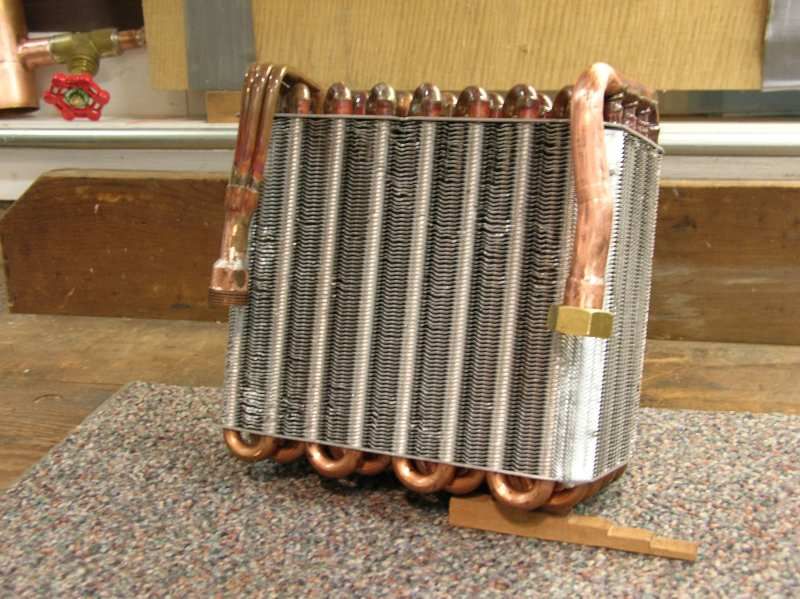
I plan to use this to cool the reflux condenser water and to do the same for the long water jacketed condenser(Leibig?) using the water pump in a closed circuit. If the cooling capacity is to small, I can add a reservoir of cold water or blow cooling air through the fins. I have used the same 1/2" copper unions. Throughout the whole system..
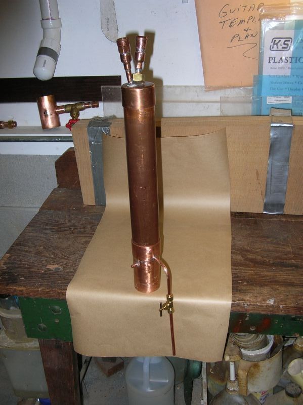
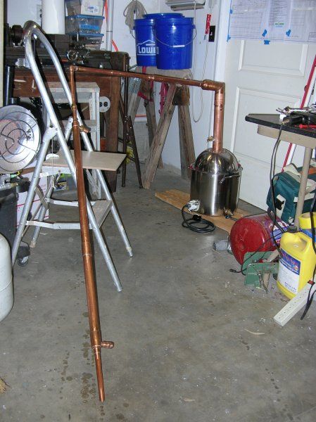
This is how the above unit will fit into the system.
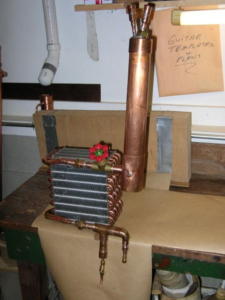
You will have to imagine the main column in place below. The stub on the lower righyt drains into the base of the column just above the boiler. The condenser is used here and on top of the reflux column arrangement. Above the takeoff valve is larger pipe for an accumulator chamber. The valve is 1/2" and may be a tad too small, we'll see.
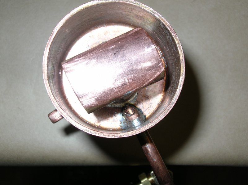
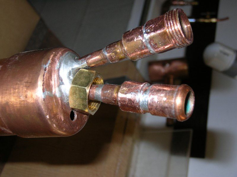
I originally looked closely at the joints in the condenser/evaporator. When I filed them down slightly, the surface was a definite yellowish, copper color and the material seemed harder than solder i.e. brazed. I took a number of pictures, but none of them show this very well. Now, I'm concerned that the material may indeed be solder. This needs further investigation. In the meanwhile, I can use the huge Leibig condenser connected directly to the gate valve and the condenser/evaporator elsewhere in the system where EtOH vapor is not present. Any advise on the braze vs solder question would be appreciated. I think I'll try and melt the stuff with a propane torch. Should melt fairly easily if solder.
Here's the reflux condenser all apart.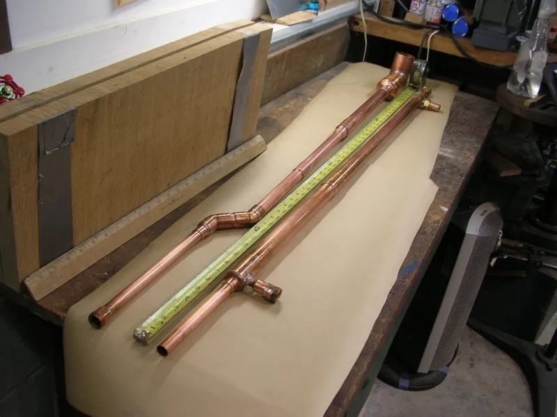
And the Boka 2 cup collector.
And the whole LM module assembled.
I think I'll have to put the remainder of the images in the next post. We'll see. Meanwhile there should be enough to think about here already.
Cheers,
McT.
The pictures are taken and I'll post a few now. Especially the now famous evaporator/condenser. Speaking of which, I in fact don't know the difference, but here's what we have.
I plan to use this to cool the reflux condenser water and to do the same for the long water jacketed condenser(Leibig?) using the water pump in a closed circuit. If the cooling capacity is to small, I can add a reservoir of cold water or blow cooling air through the fins. I have used the same 1/2" copper unions. Throughout the whole system..
This is how the above unit will fit into the system.
You will have to imagine the main column in place below. The stub on the lower righyt drains into the base of the column just above the boiler. The condenser is used here and on top of the reflux column arrangement. Above the takeoff valve is larger pipe for an accumulator chamber. The valve is 1/2" and may be a tad too small, we'll see.
I originally looked closely at the joints in the condenser/evaporator. When I filed them down slightly, the surface was a definite yellowish, copper color and the material seemed harder than solder i.e. brazed. I took a number of pictures, but none of them show this very well. Now, I'm concerned that the material may indeed be solder. This needs further investigation. In the meanwhile, I can use the huge Leibig condenser connected directly to the gate valve and the condenser/evaporator elsewhere in the system where EtOH vapor is not present. Any advise on the braze vs solder question would be appreciated. I think I'll try and melt the stuff with a propane torch. Should melt fairly easily if solder.
Here's the reflux condenser all apart.
And the Boka 2 cup collector.
And the whole LM module assembled.
I think I'll have to put the remainder of the images in the next post. We'll see. Meanwhile there should be enough to think about here already.
Cheers,
McT.
Re: Hey from Virginia
OK -- The rest of the pics.
This is out of focus, but you get the point. Not much explanation needed on the rest...
Looking at the picture, I am amazed at how big that Leibig is. Pretty big overkill.
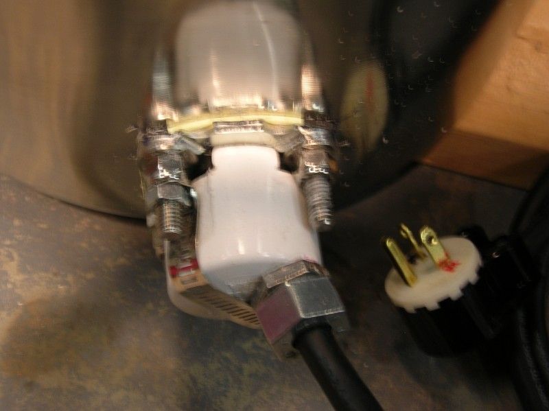
It is the pot still configuration I'll start with. The connection to the element on the boiler is just a bolt on element (ala Lowes) covered by a PVC end cap which has been filed and cut to fit around the bolts. It's held on by a hose clamp which has been cut in two and drilled for the bolts. The 3 wire cable is 220 v. with the green grounded to the element mount which electrically connects to the boiler body. The controller is in pieces with the volt/ampere meter out - offending resistor removed awaiting possible replacement.
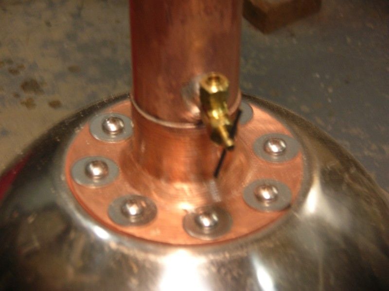
The Lyne arm is articulated and the angle can be changed. The return flow fitting is visible at the base of the column stub which attaches to the dome of the boiler. The dome sits on top of the lid which has been opened so as to provide a louvered effect between the boiler body and the dome. This should provide some degree of "Passive" reflux. I've no basis for what I did here other than to simulate, somehow, the effect of the bulbous configuration often seen in alembic stills. I doubt it will be of much effect in reflux mode.
The reflux column is removable and about 4 feet long. It has crossed 1/4" tube segments across the lower end which support a stainless screen which holds back the lava rock.
The pump well do various things from cooling condensers and heating fermentation tubs (winter) to back flushing cleaning solutions etc.
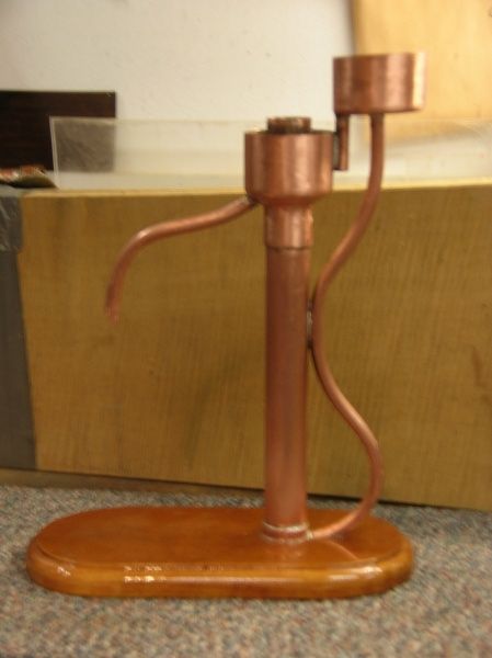
Finally a picture of my Parrot - a work of art - stolen from the forum, but pretty nonetheless.
Enough for now. I'll report back when there is some functional progress to report.
Kind komments welkome.
Cheers,
McT.
This is out of focus, but you get the point. Not much explanation needed on the rest...
Looking at the picture, I am amazed at how big that Leibig is. Pretty big overkill.
It is the pot still configuration I'll start with. The connection to the element on the boiler is just a bolt on element (ala Lowes) covered by a PVC end cap which has been filed and cut to fit around the bolts. It's held on by a hose clamp which has been cut in two and drilled for the bolts. The 3 wire cable is 220 v. with the green grounded to the element mount which electrically connects to the boiler body. The controller is in pieces with the volt/ampere meter out - offending resistor removed awaiting possible replacement.
The Lyne arm is articulated and the angle can be changed. The return flow fitting is visible at the base of the column stub which attaches to the dome of the boiler. The dome sits on top of the lid which has been opened so as to provide a louvered effect between the boiler body and the dome. This should provide some degree of "Passive" reflux. I've no basis for what I did here other than to simulate, somehow, the effect of the bulbous configuration often seen in alembic stills. I doubt it will be of much effect in reflux mode.
The reflux column is removable and about 4 feet long. It has crossed 1/4" tube segments across the lower end which support a stainless screen which holds back the lava rock.
The pump well do various things from cooling condensers and heating fermentation tubs (winter) to back flushing cleaning solutions etc.
Finally a picture of my Parrot - a work of art - stolen from the forum, but pretty nonetheless.
Enough for now. I'll report back when there is some functional progress to report.
Kind komments welkome.
Cheers,
McT.
Re: Hey from Virginia
Quick progress report.
The element controller is working fine without the meter and the boiler indeed boils water. I'll have to time a measured volume just fer grins, but it's plenty fast.
I put the torch to a blob of what would have been solder on the condenser/evaporator and the stuff just sat there and took the heat. I heated it until I could melt lead=free solder held against it and it still just sat there, SO frierndfs -- the thing is brazed or something, but that stuff's not solder.
Time for bed.
Cheers,
McT.