Page 1 of 2
Posted: Sat Feb 09, 2008 1:41 pm
by rad14701
I had the same question about the needle valve, considering how there is no reflux return back to the column... Essentially, all the valve is doing is aiding in additional cooling of condensate prior to collection... Reflux would only happen if the condenser filled completely, and that could possibly jeopardize the equilibrium of the entire column...
Nice looking column...
Posted: Sat Feb 09, 2008 2:14 pm
by Brewpastor
I don't think that is what is happening. By keeping the valve closed while equilibrium is being established the condenser fills with condensate and the liquid begins to over-flow back into the column, adding to the reflux. When equilibrium is reached and product is drawn off, whatever few ml. are in the condenser are pulled off and tossed out and the run continues. The partially opened needle valve causes the condensate to back up and the backed up condensate regulates the vapor flow. Eventually the liquid is backed up to the point that it flows back into the column and rejoins the reflux cycle.
Anyway I am excited to be getting the results I am getting and will be interested to see what others have to say about this.
Posted: Sat Feb 09, 2008 2:22 pm
by rad14701
You may be right, Brewpastor, but that sure is a large reservoir to fill in order to attain the added reflux...
Were you suggesting that you could use the condenser as a heads collector when the needle valve is closed at the beginning of a run...??? Maybe I read more into your comments than you intended...
Posted: Sat Feb 09, 2008 3:04 pm
by Brewpastor
No, I wouldn't use it as a heads collector (or I hadn't thought about it anyway) and maybe I do need a gate valve. The limit of my set-up will be running something along the lines of a flavor run. The gate lets the vapor flow be controlled, but I am not sure about my "traffic jam" control and how much reflux ratio I can get with it. I will have to play with it. But that is half the fun!
Posted: Sat Feb 09, 2008 3:18 pm
by rad14701
I guess I would be looking to use the cold finger condenser for all of my reflux and the output condenser solely for full condensation of the output from vapor to liquid... A coolant flow control valve after the cold finger would handle reflux and I would probably skip the needle valve at the outlet, but having one there definitely wouldn't hinder performance... I can see how using a gate valve before the off-take condenser would help with equilibrium, and having a needle valve on the opposite end in its place might simplify construction...
Posted: Sat Feb 09, 2008 9:20 pm
by manu de hanoi
HookLine wrote:
Manu, VM works very well, there is no problem with vapour being 'sucked' up by the reflux coil. It doesn't work that way.
Ethanol vapour above about 50% strength is denser (heavier) than air, and so wants to fall. It will prefer to go into the product arm and fall down into the product condenser, rather than rise to the reflux coil.
ok thanks.But why would the vapors prefer a bit of gravity to the sexiness of the void created by the reflux condenser ?
Posted: Sat Feb 09, 2008 10:43 pm
by cannon.co.tn
I think that you do, in fact, want a valve before the condenser. This way you won't be wasting your cooling water condensing vapors that should be refluxing as vapor. If you're getting overflow from the condenser you'll actually be a LM column, which isn't bad particularly but be sure to put a beak on the tube to make sure your liquid reflux doesn't just run down the side and gets into the center of the packing.
Posted: Sun Feb 10, 2008 6:46 am
by Brewpastor
LM Column? Please explain. Thanks.
Posted: Sun Feb 10, 2008 10:27 am
by BW Redneck
Little review of the Compleat distiller's reflux management techniques...
LM-Liquid management. Condenses all of the vapor and returns part of the condensate back to the column via a valve that can handle small quantities (needle valve). Small variations in temperature can make valve settings change, and small adjustments can have a big impact on the reflux ratio. A bok inline, a moonshine-still Valved reflux model, and the Nixon-stone offset designs are good examples.
CM-Cooling management. Places a condenser before the takeoff condenser to control how much distillate is returned to the column. Controlling the cooling supply is quite fiddly and 100% reflux is difficult to do for equilibration. An "internal reflux" design is an example, although the bottom cooling tube needs to be moved closer to the top.
VM-Vapor management. Uses a large capacity valve (i.e. gate valve) to direct the vapor itself between a reflux condenser and the product condenser. Coarse adjustments of the valve make finer adjustments to the reflux ratio due to the fact that the vapor takes up more volume per mole of ethanol than the liquid. Valve settings are pretty constant and reliable. Hookline's model is one of the best examples.
Posted: Sun Feb 10, 2008 1:57 pm
by Brewpastor
BW Redneck wrote:Little review of the Compleat distiller's reflux management techniques...
LM-Liquid management. Condenses all of the vapor and returns part of the condensate back to the column via a valve that can handle small quantities (needle valve). Small variations in temperature can make valve settings change, and small adjustments can have a big impact on the reflux ratio. A bok inline, a moonshine-still Valved reflux model, and the Nixon-stone offset designs are good examples.
CM-Cooling management. Places a condenser before the takeoff condenser to control how much distillate is returned to the column. Controlling the cooling supply is quite fiddly and 100% reflux is difficult to do for equilibration. An "internal reflux" design is an example, although the bottom cooling tube needs to be moved closer to the top.
VM-Vapor management. Uses a large capacity valve (i.e. gate valve) to direct the vapor itself between a reflux condenser and the product condenser. Coarse adjustments of the valve make finer adjustments to the reflux ratio due to the fact that the vapor takes up more volume per mole of ethanol than the liquid. Valve settings are pretty constant and reliable. Hookline's model is one of the best examples.
Thank you. I appreciate your explanations. Abbreviations are not always obvious and so this is helpful in learning the local lingo. On my way home it clicked that LM must be Liquid Management. I have to say I felt a little dumb, but sometimes I miss the obvious!
Posted: Sun Feb 10, 2008 2:19 pm
by CoopsOz
Those explanations were excellent. I get confused in the difference between CM and VM all the time. I've saved that post for quick reference in the future.
Posted: Mon Feb 11, 2008 2:16 pm
by Brewpastor
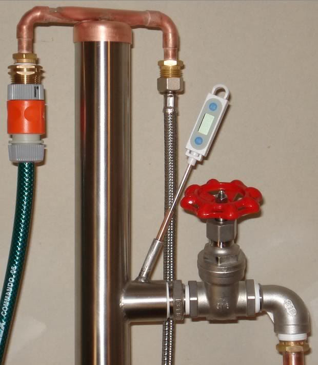
Well, I installed a gate valve today. I can't wait to give it a run. I am now stuck with a new problem - where do I put the thermometer?!
Posted: Mon Feb 11, 2008 4:13 pm
by tracker0945
Can't say where it should be but I think that where it was would not be giving you the correct vapour reading. There most likely would have been liquid dripping on it from the condenser which would be cooler than the vapour.
Cheers.
Posted: Mon Feb 11, 2008 4:31 pm
by rad14701
Perhaps between the column and the newly installed gate valve in the take-off tube... In that location it would give an accurate reading of the vapor at the point where it counts the most... You would still get a reading even if the gate valve is closed during equilibrium... You could then adjust the heat source, condenser flow rate, and gate valve in order to maintain the proper temperature, reflux, and take-off rate...
Posted: Mon Feb 11, 2008 6:24 pm
by HookLine
That is where I put mine.
http://i152.photobucket.com/albums/s197 ... 6_Head.jpg" onclick="window.open(this.href);return false;" rel="nofollow
Posted: Mon Feb 11, 2008 6:34 pm
by Brewpastor
So, if I drill or thread a hole on the column side of the gate valve I can place the probe in the vapor channel. That makes a lot of sense. But before I go drilling holes, what "systems" do you all know of for sealing the probe? I want it to be removable and therefore am thinking a simply rubber stopper in a properly sized hole. The problem is I will be drilling into the arm of the 3/4" brass gate valve and so only have a limited space to work with. Like I said, I can thread the hole and then use a threaded compression fitting of some type if that seems best. But I am thinking the KISS principle may be best here and a drilled stopped could be a quick fix.
Suggestions, illustrations, pictures or pointers please!
I really do appreciate your help on this project. It is going to be a great piece of equipment! Thanks to all.
Posted: Mon Feb 11, 2008 6:46 pm
by HookLine
I just use a few turns of PTFE (Teflon) thread tape. Works like a charm. It will work a lot better if you taper the hole a bit, so it widens out towards the top.
Not sure if you will have enough room or metal thickness on the gate valve itself. You should be able to pull a gate valve apart, and braze in a thermo tube.
Posted: Mon Feb 11, 2008 6:56 pm
by Brewpastor
The problem is the gate valve is sweated in. I can remove the guts, but that is it without major re-do. I also don't have the means to braze, so maybe it makes sense to simply drill a hole that can accept a small stopper or a Teflon taped probe. the point where I would drill is fairly thick, both the brass of the valve and the sweated copper inside.
Posted: Mon Feb 11, 2008 7:05 pm
by HookLine
I am sure you can figure something out. Wouldn't use rubber though for the stopper. You might be able to buy a pre-drilled Teflon stopper just the right size. It would also double as a pressure relief safety valve, like the cork plug did on the original design.
Posted: Mon Feb 11, 2008 7:35 pm
by Brewpastor
That is a good idea. I think I may even have a source. I will look and see what I can find before I start drilling holes however.
Posted: Mon Feb 11, 2008 8:48 pm
by pintoshine
what "systems" do you all know of for sealing the probe?
I came up with a nifty way to seal a probe.
I like to use the cheap kitchen thermometers with the corded probe.
I drill the pipe for 1/8" npt I screw in a 1/4" compression to 1/8" npt fitting.
I cut a 2" piece of 1/4" copper tubing and slide my cheap electronic thermistor probe into it. I solder the tube to the probe. I slide the nut and the compression feral onto the pipe and screw it onto the fitting. It can be easily removed when not in use. These are easy to solder to and the thermistor is down in the point. They are quite reliable. Just don't use too much heat when attaching the tube.
Posted: Mon Feb 11, 2008 9:21 pm
by wineo
I had thought of trying about the same thing,but was afraid the soldering would damage the probe.I guess you could use a heat sink if you needed.
My setup now has the probe going through a thick #9 cork,cut in half,and inside a 3/4 inch cap.It works but your idea is a much better setup.When I get a chance,Ill try it.
Posted: Tue Feb 12, 2008 5:54 am
by rad14701
I wouldn't solder the probe and would be very cautious when using compression fittings on them as well... Any pressure applied to the probe can potentially alter readings... Considering how there will be no real pressure building up behind the thermometer probe either Telfon tape or a flour and water paste mix should be plenty...
Posted: Tue Feb 12, 2008 7:26 am
by pintoshine
I had thought of trying about the same thing,but was afraid the soldering would damage the probe
These probes are oven safe to 750F. Soft solder melts somewhere in the neighborhood of 450F. As long as you are quick it solders in 5 seconds.
as far as changing the rating of the probe, I haven't had it happen yet having done it to at leasts 6 of these. The lcd part of all these has been junk. They consistantly read the wrong temp low by 2 degrees F.
I test each on and mark the lcd part with the adjustments.
That way I know when I hook it up it is going to be off by X amount.
The compression ring only touches the copper tubing and not the probe itself. These are electronic and not the mechanical types so there should not be any damage unless you pinch it in two pieces.
Posted: Wed Feb 20, 2008 3:01 pm
by Brewpastor
I will try to get a picture up, but I have put in the gate valve and placed a thermometer port between it and the column. I drilled and threaded a 1/4" hole and the screwed a threaded fitting into it (a 3" x 1/4" brass pipe) with a 1/4 x 3/8 adapter on the end. I have a teflon plug that fits into this that has a Polder swivel head digital thermometer through it. I think it will be a sweet set-up.
Posted: Sun Feb 24, 2008 5:25 pm
by GingerBreadMan
I'm thinking of building something like this myself - on a smaller scale for stove top operation. Your pics inspired me to start source parts and using the interactive calculators on the parent site

I'm not going to put in a gate valve and use a valve on on the water cooling to the 'cold finger'. I guess it would be a CM type column, where controlling the cooling would control the amount of reflux. No cooling at all to the cold finger and pull the packing and it's a pot still.
I liked the original design at the begining of the post before the modifications
- no coil to wind, simple cold finger
- no tricky plates to solder like a VM
- no expensive gate valve
- thermometer is easy to place at the tee.
Automating VM
Posted: Fri Mar 07, 2008 3:48 am
by minime
I recently received Riku's new book on ARC and his opinion is that VM is the best small scale design for neutrals. He explains several attempts to automate the VM design and discovered that a valve on the bottom of the condenser was exactly what worked. It doesn't stop the flow of vapor into the condenser but slows it down dramatically.
He then automates with the use of a temperature probe and a powered valve in that location.
He does state however that the gate valve before the condenser is essential to equalize and concentrate heads before removing product. His book is not very clear or well illustrated but it certainly has sparked my interest in some areas. He does not advise on specific valves and thermostats so I'm having trouble putting it all together but I recently got my hands on 5 feet of 3" copper "free" and would like to try a VM build with it.
?? Is there a ratio of column diameter to condenser diameter?? I can't seem to find any info. I was thinking of 1/2" X 36". Anyone have an advice for me?
Re: Automating VM
Posted: Fri Mar 07, 2008 4:52 am
by HookLine
Don't know of any specific ratio for a VM set-up, but I can tell you that the amount of vapour that goes down the product arm during a reflux run is a fraction (no more than 20-25%) of the total amount travelling up the main column. And it is also being quickly condensed, which reduces its volume by a huge amount. Only the top inch of my Liebig product condenser gets warm.
I run a 2" VM column, with a 3/4" product arm and that works fine. I am pretty sure that 1/2" would also be fine for mine.
My guess is that 1" for a product arm for a 3" column would easily cover it, you would probably find that even 3/4" is plenty.
Also the control valve at the top of the product arm does not need to be real big either. Mine is a 3/4" and is only open a small amount during a reflux run. If I was building mine again I would only use a 1/2" valve (and overall product arm), which would save a fair bit of money (and weight).
Definitely recommend a gate valve. And stainless too. Costs more than brass, but are much better valves that have all PTFE seals, unlike brass that use rubber and fibre seals. Brass valves also have to be de-leaded.