HDNB wrote:and looking a bit closer at yours, the screw on the bottom of the switch has a darker screw, and on top a lighter one. this indicates it is configured with pole 1 on top and pole2 on the bottom... or to put it another way it makes/breaks left to right...just like mine.
check this with a meter before you plug it in...or you may let the factory smoke out! (really hard to get that smoke back into the wires too)
it's hard to explain this without knowing your level of electrical knowledge...so just to be clear: your system looks like it is wired wrong!!! exercise caution before plugging in!!!! if i am not making sense with the ^^^ info, let me know, i'll draw it out better.
I have a fairly good grasp on electrical .
so I had my neighbor look at it. (told it was for brewing "beer" ) hes an electrician and had a meter with a tone. put a probe on each black terminal. when we flipped the switch the tone with go one and off. I hadn't changed the wiring since I posted the pic. so it seems like im good to go.
had me second guessing myself, so checked out leviton's site for wiring. indeed black screw is line, brass screw is load....so my cautions were worthless...sorry for wasting time, but better safe than sorry.
got a chance to finish my controller yesterday while doing (hopefully one of the last) a run on my 1500w hotplate.
got out the reading glasses and sure enough STDP switch that i had used a meter to identify make/break left to right was indeed labelled A,B,C down each side. (b had no screw) so on mine :
A/A
C/C
apparently your leviton sw would also be marked? or do they just rely on screw color?:
A B (light screws)
/ /
A B (dark screws)
anyway, special thanks to Jimbo for a really informative thread that got me motivated, and to Cranky's supplemental information that make me decide on an 80A resistive controlled SSR, a 500k Ohm pot, 25A stdp switch, fancy $12 ammeter/voltmeter, scavanged box, heatsink and fan, all wired and plugged on 8/3 cabtire.
Works a charm! comes on at 4 A and runs somewhat linear to 22A on a camdon 5500W low density element.
Can't believe it took this long to wet test this thing.
Full smoke at 21A drawdown and can boil 20L of water in about 8 minutes...that's about a 2 hour and 10 minute advantage over the old 1500W hotplate!
the pot is pretty touchy, but i can get down to 3A before it drops out.
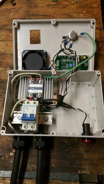
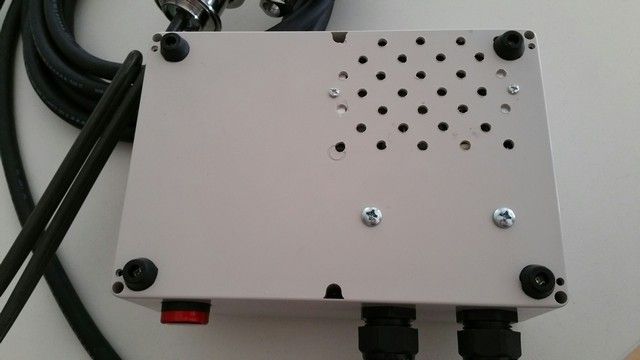
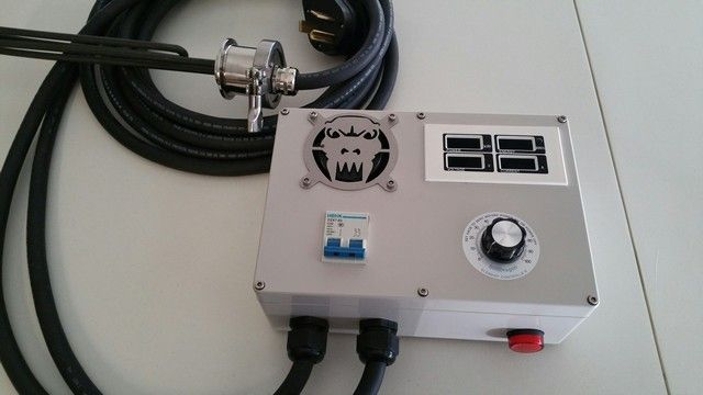
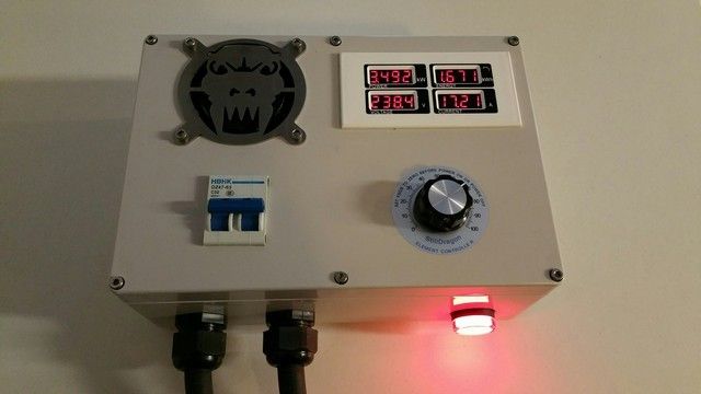
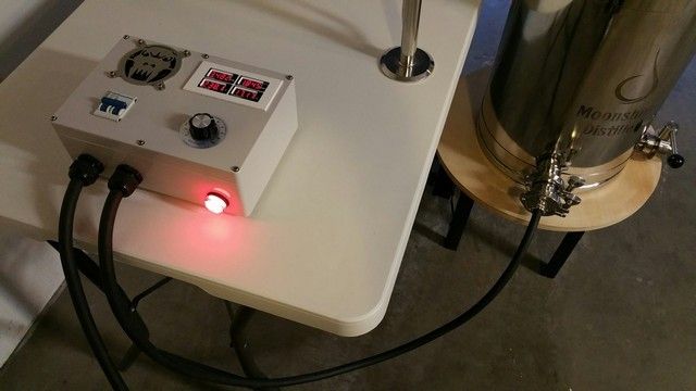
Over the last weeks I ordered the parts and assembled a phase angle controller. I was inspired by many others here and by other resources found on the internet. A circuit breaker was used for an on/off switch to add a level of protection. The SSR and heat sink got a 220v fan for cooling. I found a cool led ammeter/volt meter combo that also computes and displays watts and kilowatt hours. The ammeter unit is sensing the non-SSR side of the power so it doesn't get burned out by the SSR's spikey power. The ammeter unit gives me a repeatability that helps with overall control immensely. The red indicator light was added just because I could. The power cord I found at the home improvement store was a bit more expensive but is super nice, bendable at all temps, and is very safe. It required PG21 glands.
A coping saw was used to cut out the square holes, a router cut out the fan hole, and a step drill bit or regular drill bit cut the round holes. I found the fan grille online and thought it was fun. The controller finished nicely.
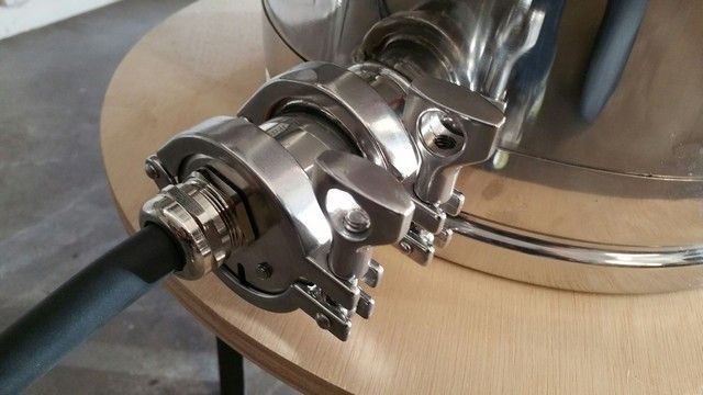
The element is a ultra low density 5500watt beauty that was treated to a wonderful looking protective guard. The element is grounded to the inside of the guard and it has a drain groove if things ever leak. I did have to machine out the hole the element guard came with to accept the larger stainless PG21 gland I used.
During the initial run I distilled some water to test its function. It never got hot and performed wonderfully in every way. I will not run it full out for fear of scorching but wow, what a change from propane. I should have done this project long ago. Thanks to the forums for your examples and help with this project.
Project Galileo wrote:The element is a ultra low density 5500watt beauty that was treated to a wonderful looking protective guard. The element is grounded to the inside of the guard and it has a drain groove if things ever leak. I did have to machine out the hole the element guard came with to accept the larger stainless PG21 gland I used.
Wow very nice build PG. Could we get a pic of this element guard broken down? Where did you get it?
Thanks for the compliment. It was a fun build. I did not take a picture of the element guard broken down. The element guard kit is from Still Dragon. Their website does have a picture of the kit broken down.
Well just finished the box just have to do so me minimal wiring. The giant fan on back is 220 so I didn't have to dick around with wall worts and what not. That thing is crazy heavy duty. I'm gonna have to screw it down so it doesn't take off, and yell contact before I turn it on.
You do not have the required permissions to view the files attached to this post.
Life is a journey you take alone. Make sure you do what you what makes you happy
Here is mine FWIW. A lot of the parts were scrounged from my junk box like the wire, wire ferrules, terminal blocks, DIN rail, pot and knob. It doesn't need a fan, the highest temp that I measured (using a 30awg thermocouple between the SSVR and the heat sink) was 64 deg C during a long reflux spirit run using a 5.5Kw element and pushing 3.3 Kw into it. I got a larger box in case I want to add a PID controller and an SSR that I have lying around for temp controlled mashing.
Controller_Outside-Resized.JPG
Controller_Inside-Resized.JPG
You do not have the required permissions to view the files attached to this post.
Well, here's my nasty looking box. Most of what you see was found in my junk pile. Old military ammo box, the tachometer face from my old racecar and the rest just copies Crankys simple controller.
This project started out as a simple back-up unit for my tow current SSVR's that get whored out to brewing, distilling and maybe the occasional crab boil. Suffice to say in the spirit of the hobby it kinda grew a little. Sorry no temp gauges besides the one on the pot, and I pay little attention to that anymore.
My off-the-shelf junction box, housing an Auber Digital SSR with a 40A SSR relay, all 4-wire 10 AWG cords running out to a (currently) Stainless 4500-Watt/240-Volt Low Watt Density Fold-Back in an SD housing.
Control3.jpg
You do not have the required permissions to view the files attached to this post.
People say that I'm a bad influence. I say the world's already f#cked -- I'm just adding to it.
here is mine after scrapping another idea and frying my relay or so I think. Bought a couple cheaper ones to try and would like to be sure of wiring.If anyone can look at it and tell me how I can run my last few wires that would be great.The heat sink is on outside of box and will have all grounds running through it (attached to it). I believe that one of the black wires should run through the current transformer. What I don't know or understand is supplying the power to the volt meter. When I tried it before it sparked on me. Would love to get it right this time. I have looked at lots of schematics and well most confuse me and fries components so if you can help great!
No offense intended here Guilty but could you post those pix on HD instead of a 3rd party host? On my computer it looks like most of your pictures have been deleted by the host you are using.
cranky wrote:No offense intended here Guilty but could you post those pix on HD instead of a 3rd party host? On my computer it looks like most of your pictures have been deleted by the host you are using.
+1.
Or, when the photos are deleted from a 3rd party host, it leaves something like this in its place:
You do not have the required permissions to view the files attached to this post.
Here's a picture ogf the main bit of one of mine, the still plugs in as can be seen and has it's power set to full. (Don't worry about the thermostat - )
Controller resize.jpg
You do not have the required permissions to view the files attached to this post.
Cranky I looked here on how to post pics and tried a few but did not work. It seems that tiny pic will only allow one photo on here .Will try something else and see. even try some more searching of the site for how to do it.not computer literate really with code
Here's the setup I've been using the past couple of years.. used an old cash box 7" x 10" x 4.5"..
You do not have the required permissions to view the files attached to this post.
" I know quite certainly that I myself have no special talent. Curiosity, Obsession and dogged endurance, combined with self-criticism, have brought me to my knowledge and understanding "
Guilty wrote:have you put up a wiring diagram anywhere?
The wiring is standard wiring for this setup..
Guilty wrote:it looks like four wires on pot.
Yes there is four wires.. one is ground.. the others is one for power coming in, the middle one transfer power to the third for connecting to the second pot..
Guilty wrote:Why the loop to connect two together?
The loop to the second pot is for finer tuning.. the main pot (bottom) is a 470k 2 watt, and the top pot (just under the meter) is a 47k 2 watt pot... this setup allows for fine tuning (easier to set) of your power usage..
Mars
" I know quite certainly that I myself have no special talent. Curiosity, Obsession and dogged endurance, combined with self-criticism, have brought me to my knowledge and understanding "
" I know quite certainly that I myself have no special talent. Curiosity, Obsession and dogged endurance, combined with self-criticism, have brought me to my knowledge and understanding "


