My plan for a VM unit - any suggestions?

Vapor, Liquid or Cooling Management. Flutes, plates, etc.

Moderator: Site Moderator

Post Reply
mrdrbubba
Novice
Posts: 18
Joined: Thu Jan 06, 2005 2:41 pm

My plan for a VM unit - any suggestions?

Post by mrdrbubba »

So I'm looking to put together a VM unit, all copper, and the price of 2" fittings is amazing me. Heck, the price of 2" pipe - it's looking like 5' of 2" pipe alone is going to run me upwards of USD30 - seems excessive.

But I digress. Point is, before I start scurrying around town picking up all these not-so-cheap parts, I'd like to run my plan past the experts.

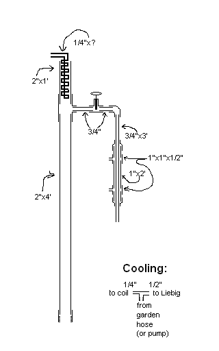
My plan (not drawn to scale):

Image

I saw someone's diagram which showed a support towards the bottom of the Liebig - how necessary do y'all think that'd be for mine? I only plan for the horizontal arm to run far enough for me to comfortably solder in that gate valve - no more than a few inches - so my instinct would tell me that weight of the arm wouldn't strain the joints TOO much ...

OH - also - I'm sure I've just overlooked this in my reading, but what if I put a reducer on the bottom of the column to take it down to, say, one inch for the screwing-in bit? The matching fittings for my boiler(s) would be cheaper that way ... and the vapor velocity from that bottleneck would come back down as soon as it hit the wider section of pipe in the column, wouldn't it?


Sorry for rambling on ... I think it's probably a sign of my excitement at the prospect of building a real reflux head after all this pot stillin' ... thanks for any and all input.
LeftLaneCruiser
Swill Maker
Posts: 231
Joined: Wed Oct 27, 2004 6:11 am
Location: Fryslân

Re: My plan for a VM unit - any suggestions?

Post by LeftLaneCruiser »

mrdrbubba wrote: I saw someone's diagram which showed a support towards the bottom of the Liebig - how necessary do y'all think that'd be for mine?
I think the diagram you saw was mine. The support isn't necessary, i don't use it myself.

Your plan is looking good, nothing to add here. And as for the narrower connections to your boiler; we share opinions on that one.

Good luck building the rig.

KJH
Grayson_Stewart
retired
Posts: 1030
Joined: Sun Oct 24, 2004 10:56 am

Post by Grayson_Stewart »

As leftlane said the support isn't necessary but can be a good idea since this column should last long enough to pass to your grandkids. The support would simply make the column stronger and prevent "oops" from bumping the condensor during cleaning and storage, also there is the added weight of water filled hoses tugging and the water in the condensor to consider.

I don't like the reduction idea. I used the same size fittings all the way through. You are correct when saying the vapor will slow back down as it passes the bottleneck area. However, the purpose of this type column is to strip the alcohol from the wash and send everything considered waste back down the column. So all that vapor has to get past the returning liquid and it could cause localized flooding in the column. The constriction would create a bottleneck and I always percieved the faster vapor flow would further impede the waste liquid flow back into the boiler. Some may have done this, but I chose not too.
Light travels faster than sound. That is why some people appear bright until you hear them speak.
Rocky_Creek
Rumrunner
Posts: 511
Joined: Thu Apr 14, 2005 5:40 am
Location: The Confederate by God States

Post by Rocky_Creek »

Very similar to one of mine that gives good results, except that my top condenser is a liebeg. A 20 foot length of 2inch copper is about 80 dollars at my local plumbing supply. 2 inch fittings unreal but worth it in the long run.
You can fool some of the people all of the time, and all of the people some of the time, and them's pretty good odds.
boozer

Post by boozer »

Hi mr---

Allow me to throw in my 2cents worth.

1 Go with the 2” brazing bush at the bottom, it will provide a more stable support for your column, make accessing your mesh easier and only cost a couple bucks more. Money well spent.

2. My understanding is to offer the vapour two about equal paths and then control the side path. Therefore I would place a 1” restriction (2”x1” washer) just above your side path. Then the gate valve will have more control. With your current set up you will have a max potential of 12% of vapour passing through your gate valve when it is fully open.

3. There is no point in splitting the water, run them in series, liebik, reflux, from the bottom up. As the liebik will only handle about 10% of the heat input it will have little effect on the cooling in your reflux.

4 My reflux condenser is 9x3/8 tubes of 210mm each arranged in a circle with in a 2” pipe (vapour passes through the tubes). It can handle 2400W. This allows the reflux condensate to fall into the dam I created by using a 2”x1” washer (see 2 above).
A needle valve off this dam provides LM and a path for foreshot collection.(keeps product path clean.

5. keep the horizontal path as short as possible and allow at least 6” vertical path before your liebik. I haven’t any brace on mine. I used 1’’ pipe off the column to provide a larger footprint and hence more support.(soldering, not brazing which anneals the copper and makes it soft)

I you like I can tell you how to make the whole thing just out of pipe without any bought copper fittings;just ask.

Good luck
Bottoms up; boozer
rkr
Bootlegger
Posts: 104
Joined: Sun May 22, 2005 11:39 pm

Post by rkr »

That's not actually the case. When alcohol vapors reach the condenser they turn to liquid meaning that their volume decreases considerably. This in turn causes "suction" in VM arm and makes the pipe diameter ratio irrelevant. As an example my air-cooled VM still has only 15mm ballvalve in 54mm column and it produces ~1 liter / hour with 1kW.

- Riku
boozer wrote:Hi mr---


2. My understanding is to offer the vapour two about equal paths and then control the side path. Therefore I would place a 1” restriction (2”x1” washer) just above your side path. Then the gate valve will have more control. With your current set up you will have a max potential of 12% of vapour passing through your gate valve when it is fully open.


Good luck
Bottoms up; boozer
boozer

Post by boozer »

Hi Riku

If both paths are opperating under the same effects of condensing vapour to liquid and both paths are open to the atmosphere at their terminals, how could a vacum be selective in sucking more vapour to the VM path rather equalise the imbalance by inhaling air from the atmosphere.

But hey if you are getting 1 litre/ hour how about posting a descrition of your rig and I will convert to your set up.

Regards,
bottoms up; boozer
rkr
Bootlegger
Posts: 104
Joined: Sun May 22, 2005 11:39 pm

Post by rkr »

Hi Boozer,

The suction will naturally happen from both directions. The point is that this will cause a pressure difference inbetween the column and the VM arm which will further increase the speed of vapors in VM arm making the valve size somewhat irrelevant. Basically the valve works as a throttle body to use automotive terms.

My system is one of the options for my new ARC system. I'll probably publish details and building instructions next autumn with a new version of my book. Basically the system is quite similar to the picture in this thread. There's a collar below the condensers (convectors) to guide the reflux into middle of the column. The valve has threads and it is threaded directly to column side above the collar. After that there's about 60cm downpipe and cooling spiral. I used small valve since I had one lying around while I built this and also since I wanted to see if it would work. There's no downside in using somewhat bigger valve, it's just that you don't need expensive 2" valve to achieve 1/1 reflux ratio.

It's actually somewhat missleading to quote operating speeds with systems that automatically adjust reflux ratio. In my example I get 1 liter/hour at the start but it still takes 8 hours to process 25 liters mash since the output slows down as the mash% decreases.

- Riku
linw
Swill Maker
Posts: 372
Joined: Sun Oct 24, 2004 2:10 am
Location: Wellington, NZ

Post by linw »

Like Boozer, my VM still has the reduction washer above the take-off pipe. One of its functions is to redirect the condensate into the centre of the packing as the inner edge is peined downwards to (hopefully!) accomplish this task.

Another thought. Where is your thermometer going? Make sure you provide for that. Mine has a brass tee screwed into a nipple that is welded into the column. The vertical arm is attached to the Liebig and the thermometer is inserted horizontally through the tee arm.

Good choice, VM. Very easy to make and control.

Good luck with your building.
Cheers,
Lindsay.
mrdrbubba
Novice
Posts: 18
Joined: Thu Jan 06, 2005 2:41 pm

Post by mrdrbubba »

Ah - thanks very much for all your input.

The thermometer had completely slipped my mind - although I've always done without on my potstill. D'ya think if I cut a hole in my insulation and used one of those surface thermometers - like for a grill - I could add it on later, if I can't get the feel of the thing on its own? Again, I've never worked with a reflux still before, but I've never used a thermometer either.

As to the reduction washer - whether or not the effect on the vapor path is significant, the fact that it channels the refluxed condensate towards the middle of the column sounds good. Unless there are any real downsides to it - which it doesn't sound like there are.

Boozer, I'm very interested to know how to make it out of just pipe as you mentioned - but my metalworking skills are quite limited. I've only even soldered three or four joints, and I'm intimidated even thinking about much beyond that. But I'd love to know, even if I can't pull it off. Also - that reflux condensor you described - I'm having a hard time visualizing it. Does cooling water flow through the tubes, i.e. are they a closed system connected to themselves? Or is it an air-cooled sort of thing?

Again, thanks so much - I'm starting up a nice big sugar wash in anticipation :-D
boozer

Post by boozer »

Hi mrd---

My condenser is fabricated with the 9 tubes brazed into two circular end plates (flattened out piece of 2” tube wall) which had 9 x 3/8 holes drilled in them in a circle. (yes with 2mm gaps between tubes). At the top they are flush with the top plate. Their bottoms were cut at 45* and protrude through the bottom plate by ½”, that means any condensate formed in a tube runs down its inside and drips off the point formed by the 45* cut. These points are arranged so the drips fall within my dam and do not fall back through the 1” hole to the packing. This fabrication, pipes and plates is inserted into a 2” pipe (about 3” longer) and the plates brazed inside the 2” pipe. Basically water is feed in at the bottom and out at the top, but with a bit of manipulation to get the water to flow evenly around all tubes. I use this form of condenser because it has a low resistance to water flow and suits my recalculating pump. I’m told it is more efficient to set it up the other way with water in the tubes but that means making end tanks.

To make a joint in 2” pipe so you can pull your rig apart for ease of storing, cleaning etc is easy. It’s better if you have some way of cutting your pipe square. Cut a slot 8mm wide(suits my pipe) down the side of a piece of 2” pipe for a distance of 30+mm. cut the 30mm length off the pipe. Squeeze it so its slot closes and push it 10mm into what will be the top section of your apparatus. Solder it in but don’t get any solder on the exposed portion. Wrap six turns of plumbers tape around the reduced section and push it in to the lower part of your column. Presto vapour tight removable joint.

To attach your gate valve; buy a brazing bush of the size to screw into your gate valve, Solder it on the side of your column, drill out the hole through it into your column and file it. Presto no expensive 2x2x 1 copper T.

To make a 90* bend for the turn down; cut a piece of 1” tube at 45* (make a mitre box?).Rotate one end through 180*, mate the cuts together and solder. Presto a 90* turn.

Liebig ; get a piece of ¾ tube the length required for your liebig, say 400mm, Anneal the ends (heat red hot and let cool) and flare them until they are a tight fit inside the 1” water jacket. Get a 2” length of ½ copper flare one end so it’s a tight fit inside the ¾ tube (your product spout).
Drill two 8mm holes in the 1” tube say 380mm apart. Cut 2 pieces of 3/8 tube 50mm long. Cuts their ends at an angle and file to fit the 1” tube at a tangent (increases foot print on 1’tube) 3/8 plastic tube push fits on them. Solder or braze it all together.

Ok it might be really basic to guys who have built a few stills, but for those who haven’t it can save bucks if that is required and adds pleasure in being creative and “making” your own. The hooch will taste better.

Bottoms up; boozer
rectifier
Swill Maker
Posts: 205
Joined: Sat Apr 30, 2005 4:50 pm
Location: BC, Canada

Post by rectifier »

I like your 90deg turn idea, as well as soldering and then drilling to get the valve on. Could build quite a bit cheaper just with those 2 changes. Good thing I haven't started on my reflux still yet
mrdrbubba
Novice
Posts: 18
Joined: Thu Jan 06, 2005 2:41 pm

Post by mrdrbubba »

Wow - that's a lot of good ideas that never entered my mind. Thanks, boozer. I don't think I have the tools to flare the tube, but beyond that - especially saving on T's - this'll save tons.

I put the valve and the Liebig together tonight - hopefully it won't be much longer before I'll have a nice shiny new head to show off here :D

Thanks again boozer - and all!
Guest

Post by Guest »

One aspect of flow control is using a smaller valve in a larger tube to provide more linear control. A full size valve will be less linear which should not create a lot of trouble just have to get used to how to set it. It may be quite difficult to obtain copper valves. Brass is much more common. Not sure what valve that is maybe a gate? Globe and plug are considered flow control, gate is an isolation as is ball. Beware a globe may have rubber in it. It may be worth asking the board what type valves they have used sucessfully in the given application.
mrdrbubba
Novice
Posts: 18
Joined: Thu Jan 06, 2005 2:41 pm

Post by mrdrbubba »

Thanks, guest, for pointing that out -

I had planned on using a full-sized (3/4") gate valve, which I believe one of the descriptions I'd read had called for. Out of curiosity, once I bought my valve, I calculated the cross-sectional area as a function of turns of the valve handle, and found the change to be only slightly off from linear - I assumed, therefore, that it would give me fairly intuitive control over the vapor flow. I may well, however, be wrong. Either in my calculations or in assuming that CSA properly reflects flow.

It's not too late for me to switch out valves, if gate valve was a bad idea ...
Guest

Post by Guest »

Stay with your 3/4 gate valve. The control will be excellent ,plus you have the facility to open it fully to increase your flow when doing a stripping run or getting your tails out quikly.
Your on the right track mate.
linw
Swill Maker
Posts: 372
Joined: Sun Oct 24, 2004 2:10 am
Location: Wellington, NZ

Post by linw »

mrdrbubba wrote:Thanks, guest, for pointing that out -

I had planned on using a full-sized (3/4") gate valve, which I believe one of the descriptions I'd read had called for. Out of curiosity, once I bought my valve, I calculated the cross-sectional area as a function of turns of the valve handle, and found the change to be only slightly off from linear - I assumed, therefore, that it would give me fairly intuitive control over the vapor flow. I may well, however, be wrong. Either in my calculations or in assuming that CSA properly reflects flow.

It's not too late for me to switch out valves, if gate valve was a bad idea ...
I use a 3/4" gate valve and it works fine. You only need a very small opening for the run. My valve is only open 1 turn for good separation and stable temp.
Cheers,
Lindsay.
rkidtech
Novice
Posts: 67
Joined: Sun May 08, 2005 12:20 am

Re. Vapour Management

Post by rkidtech »

Hi mrdrbubba

I found this on a distilling forum about a year ago and I can’t remember who posted it so if Mike N recognises this thank you. The question asked was:-
Can anyone please explain the working principle of a vapour management still head. What are its advantages/disadvantages over
the nixon-stone type?
I've seen pictures of this type of head on http://homedistiller.org onclick="window.open(this.href);return false;" rel="nofollow but have yet to find a description of how they work.
=====================
Here we go. I'll try and make it as short as possible.
If you feed vapour to the middle point of a horizontal tube, then it will split into two streams.
If the cross-sectional area of one arm of the tube is A and the other is B, then the vapour will divide in that ratio, A/B.
You can control that cross-sectional area by means of gate valves, and this is useful for some applications.
If you feed vapour into the middle point of a vertical tube, density now becomes a factor and this can be used to control the behaviour of a distilling column depending on the composition of the vapour inside.
First thing to note is that vapour rises in a distillation column not because if convection, as some think, but because it is pushed by vapour generated in the boiler. All vapour in a distillation column therefore rises at the same rate no matter what its density, and at a rate determined by the power pumped into the boiler.
When vapour meets the middle point of the vertical tube, some will be driven further up the column and some will enter the tube. In practise, this middle feed point is sealed off by a gate valve in a side arm during stabilisation of the column, and the vertical tube comprises the path up to the top condenser and the path down to the product condenser. It is a 'kinked' vertical tube fed with vapor at its middle point. When the gate valve is opened, vapour enters the side arm and, if it is less dense than air, will try to rise. If it is denser than air then it falls. It cannot rise in the side arm as that arm only goes down, but can fall as it points down to the product condenser and collecting vessel. The gate valve controls amount that can enter the side arm.
The relative densities of steam at 100C, air at room temperature, and ethanol vapor at 78C are 0.6/1.0/1.6
If the vapour in the column is ethanol, then it will fall down through the product arm, and if it is steam then it will continue up to the top condenser. The changeover point, when the vapor in the column is the same density as air, if when the vapour comprises 45.5% ethanol and 54.5% steam. The volume of vapour falling down through the side arm therefore tails off and finally stops as the vapour mix in the column approaches and then reaches this point. As this represents the onset of tails, the side arm being at the top of the column, a vapour management still automatically stops delivering product before it is contaminated with a significant amount of tails. It is also the reason why you cannot test the operation of such a still using steam alone. Subsequent collection of tails can be done by turning off the top condenser, blocking that path with a rag in the top vent, and fully opening the gate valve. A rag is recommended for blocking the top vent as a gate valve would present the possibility that both gate valves could be closed together, sealing the whole still.
Sorry if that still seems long winded. I would seriously welcome any summary that manages to cover everything more concisely.

Mike N


That about sums it all up
Cheers Geoff
Post Reply