Bit of a long first post, but here we go...
Been seriously reading about distilling for quite a while now, mainly here and at homedistiller.org (and a big thanks to Tony Ackland). I am impressed by the distilling knowledge and craft skills of many of you guys, and it is almost entirely guys, isn't it?
I have a trade/engineering/science background and interests, so this sort of thing is right up my alley. Small scale home distilling has to be pretty close to a backyard tinkerer's heaven, sure beats tuning the car for the umpteenth time.
I am not a big drinker, just the occasional 1-2 for me, no danger of me ever being an alco, but the prospect of cheap, clean, low-hangover booze is still pretty appealing.
I also use about 5-6 litres of methylated spirits a year for cleaning purposes, sterilising plant grafting knives, etc, and I would love to have a supply of cheap, high purity, high strength, RESIDUE AND STINK FREE ethanol instead of the adulterated crap that is commercial methylated spirits.
I also have an increasing interest in bio-fuels (being able to distill could be useful for that alone before too much longer).
And then there's that tinkering thing.
So all up, you got me hooked!
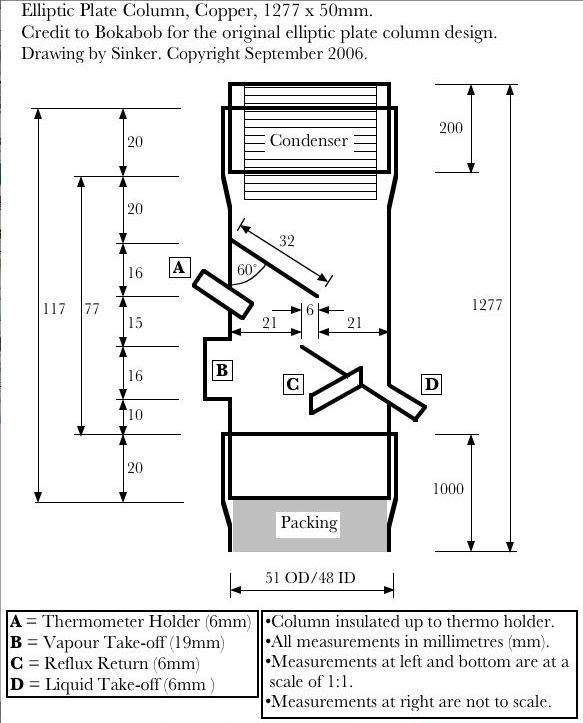
There are two basic designs that appeal to me as a first still, the Bokabob elliptic plate, and the 45º offset Nixon-Stone valved reflux.
I am currently leaning to the elliptic plate (EL) column, with some modifications, including a fixed upper plate, increased size, and allowing for a future vapour management (VM) port.
Stainless steel (S/S) construction would be nice, but I don't have access to a TIG welder, while I do have access to a friendly plumber, cheap custom cut copper pipe, and brazing equipment.
I will learn to use liquid management (LM) first to understand the behaviour of a basic reflux/fractionating column, and then later add on the VM.
Heat source will be 2000-2400w of electric elements run flat out to bring the boiler with sugar mash to the boil, and then the power level will be cut back to 800-1200w for the main run.
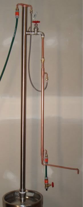
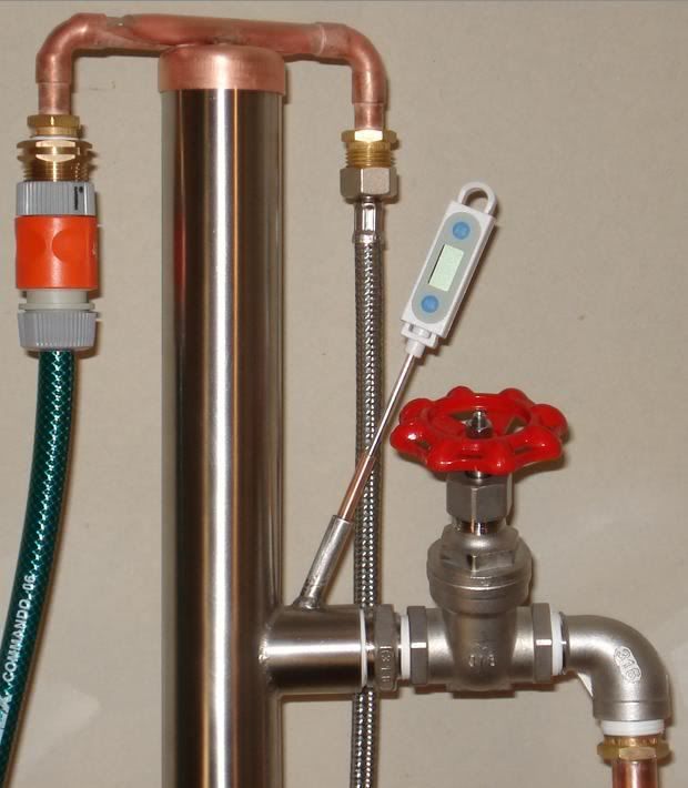
Here is my design so far:
http://i152.photobucket.com/albums/s197 ... gn_v11.jpg" onclick="window.open(this.href);return false;" rel="nofollow
I am interested in any comments or suggestions you may have about this design.
The specific issues/questions I have are:
1. I have one concern about Bokabob's EL design. It has a 1/4" (6mm) vertical clearance between the two plates, for a 1&1/2" diameter column.
I don't see the advantage of such a small, and apparently quite constricting gap. If anything, it would seem to be a disadvantage. Or have I missed something?
Is there a particular reason for having the vertical clearance this small?
Is there any reason not to make the clearance much larger, say 15mm (for a 50mm column), as I have done in my plan? Or even 20mm?
My understanding is that the optimal speed range of vapour flow up a column in ethanol distillation is about 250-400mm per second (10-16"/s). This is not fast, just a gentle breeze. Is this speed range simply too slow to be affected by the constriction?
The valved reflux offset Nixon-Stone style of head avoids any possible problem of constriction by being the same cross-sectional-area all the way through to the condenser. But is this a significant advantage at the low vapour speeds being used?
2. I notice some people set their elliptic plate angle at 45º, instead of 60º (off vertical, equals 30º off horizontal). Is there any advantage to 45º?
3. What is a good size (internal diameter) for the thermometer holder tube?
4. Is 19mm (3/4") the best size for a VM take-off port on a 50mm column?
5. Has anyone had any problems with the non-soldered flange/socket type joints I have drawn for joining the 3 separate column sections together? (The joints will be sealed with either PTFE tape, or dough, during use.)
How deep should the flanges be? How far should one section slide into the other? (I have them at 20mm in the drawing.)
6. How much contact with copper does the ethanol vapour/liquid need to get conversion of sulphides?
Given that my column is going to made entirely from copper, if I use copper mesh packing in the column, do I need to use it for all of the packing, or can I use for just the top 25-30%, and use S/S scrubbers for the rest? Indeed, do I need copper packing at all in an otherwise all copper still?
Is it just a case of more contact with copper during distillation is better?
And lastly, and at the risk of restarting old battles and getting shot at, (takes deep breath), two comments on...
7. Silicon bronze. (UNS number C65500 in particular, but possibly anything from C64700-C66100.)
I have been doing some reading about silicon bronze alloy (not silicone, silica, or silicate), and I cannot find any reason not to use it. Its basic composition doesn't seem to be a problem (96% copper, 3% silicon, 1% manganese, sometimes iron or nickel). It is a very inert material with excellent resistance to degradation under a wide range of physico-chemical conditions, has a similar ductility to plain copper but a higher strength, and is used to build containers to hold strong chemicals. It certainly doesn't seem any worse than standard brass or plain copper from a health point of view, and may even be safer.
If silicon bronze is safe, then:
a) its high copper content might help remove sulphides from the ethanol (assuming the copper component is not rendered too inert by the additional alloying components); and
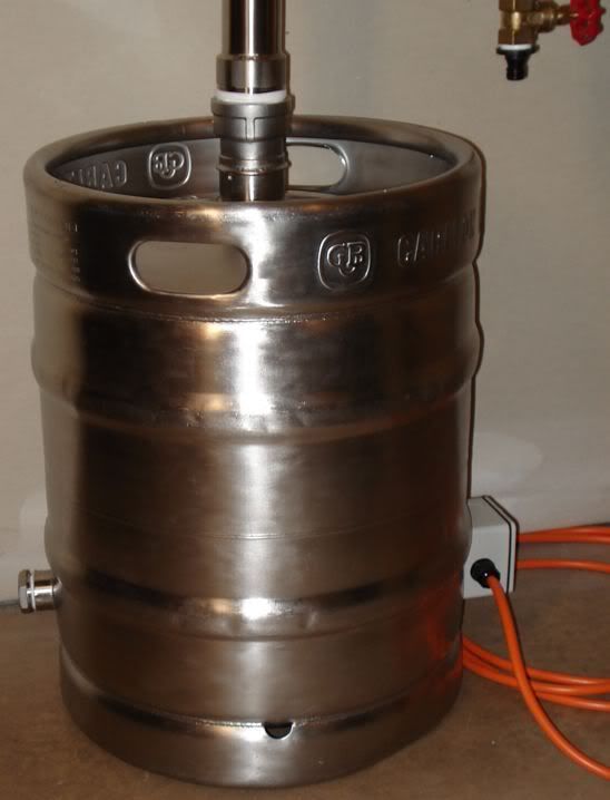
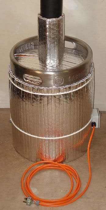
b) second-hand, silicon bronze, electric hot-water tanks could be good and cheap boilers.
My plumber friend can get new, fully insulated, 50 litre silicon bronze tanks, with a 2400w S/S element, very cheaply (old stock that ain't selling, everyone is going to solar hot water around these parts), and I am seriously considering getting one of these for my boiler.
The only thing to be careful of would seem to be making sure it has no lead residue on the inner surface, and the health authorities (in Australia) would be pretty unlikely to allow much free lead on the inner surface of a domestic hot water tank in the first place.
I will be using silicon bronze rods, the type used by plumbers on copper drinking water pipe, as my brazing filler.
Perhaps The Chemist could comment on this issue?
http://www.corrosion-doctors.org/MatSel ... bronze.htm" onclick="window.open(this.href);return false;" rel="nofollow
http://www.budgetcastingsupply.com/Metals.htm" onclick="window.open(this.href);return false;" rel="nofollow
http://www.suppliersonline.com/property ... #chemistry" onclick="window.open(this.href);return false;" rel="nofollow
http://www.copper.org/applications/arch ... intro.html" onclick="window.open(this.href);return false;" rel="nofollow
http://www.copper.org/resources/propert ... asses.html" onclick="window.open(this.href);return false;" rel="nofollow
http://www.russianbells.com/founding/bronzealloy.html" onclick="window.open(this.href);return false;" rel="nofollow
http://periodic.lanl.gov/elements/" onclick="window.open(this.href);return false;" rel="nofollow
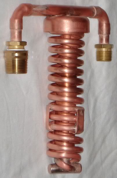
8. Condenser coil shapes.
My point here is not a major one, just a minor one about efficient use of resources.
I am not convinced that everyone in the online distilling community understand how a heat exchanger (condenser coil) works.
I had a nice job many years ago fixing medical and laboratory equipment. Some of this equipment had various kinds of heat exchangers in them, that dealt with various kinds of fluids (gases and liquids) moving around in various kinds of ways. (I kind of already knew the basic principles of distilling before I came to this site. Though I had never read up the detail or done it myself.)
Some of the condenser coils on display here, while very impressive in their construction, and no doubt very effective at their job, seem to me a little on the large side. I understand the need to have a good margin of error, especially for backyard stuff like this, but some of those coils are huge.
An substantially oversized condenser coil has three downsides. First, it wastes increasingly expensive copper. Second, it can waste precious column height, and every 100mm or so of lost packing height is a lost plate (HETP). Third, it may need a more powerful coolant circulation pump.
The main problem is the lack of a proper gap between the adjacent winds of the same coil, and also between the inner and outer coil in a double coil.
If you want to maximise heat exchange efficiency, (that is, minimise the resources required to shift a given amount of heat), then you have to maximise the area of heat exchange surface that the fluid (vapour) will flow around and across for a given size (overall length) of condenser coil, and you can't do that if half the surface of each coil winding is resting hard up against adjacent windings, preventing vapour flow around and between them.
Gap-free coil windings mean you have to use a longer coil, or colder coolant, or faster coolant flow, to do the same amount of heat exchange with same diameter coil tube.
For small tubes, around 6-10mm diameter, the gap between a heat exchange surface (the surface of the tube) and any other surface should be about equal to or slightly less than the diameter of the tube. This is for a vertical coil, like the ones used in many stills, where the coils are stacked on top of each other. Horizontal coils, where the coils are stacked side-by-side, can be spaced a bit closer but still need a decent air gap.
It will probably also improve coil efficiency if you solder some small angled deflector vanes somewhere in the bottom half of the condenser to give the vapours a horizontal twist and get them turning around the coil, in the same direction as the coil is wound (with the wind, not against it). This makes the vapour take a much longer path to the top of the condenser, and pass over much more heat exchange surface lower down.
In the same way as going up to the top of a circular building by a lift is a much shorter distance to travel than walking up stairs spiralled around the walls to the top.
The angle of the vanes would be fairly critical, around 35-40º off horizontal would be my initial guess, and the number and spacing would also be important. The idea is to get the vapour travelling as close to parallel to the coil tubing as possible, without constricting vapour flow (sound familiar?). The vanes will also double as coil positioners, keeping the coil in the centre of the column, and will also help exchange more heat (by increasing heat exchange surface area).
Less copper, less money spent, a little more packing height, and a slightly better product.
I am going to put my money where my mouth is and build a single coil, 200mm long, from 6mm tubing, with good spacing between adjacent winds of the coil, and deflector vanes. The only tricky bit is picking the angle of the vanes. Nothing like a hard objective experiment to sort the guessers from the genuinely insightful. I'll let you know which one I am after the experiment.
My aim with these comments on coils is to minimise the amount of copper, and the amount of column height needed to do the job of condensing.
Okay, your turn. Fire back.
But seriously, that covers all the questions I have left before I start building.
Thanks in advance for any help you can offer.
Elbows up!
