2" bubble cap still

Vapor, Liquid or Cooling Management. Flutes, plates, etc.

Moderator: Site Moderator

Post Reply
Chasin' Tales
Novice
Posts: 30
Joined: Wed Dec 30, 2009 12:36 pm
Location: dark side of the moon

2" bubble cap still

Post by Chasin' Tales »

First post from a long time lurker.

I had been using a 2" Bokabob slant plate column w/ good results. Decided to do a bit of experimenting. Here's the result of having the month of December off with nothing to do...

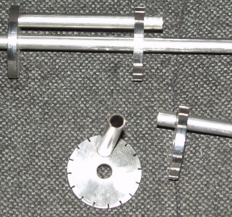
Started by cutting out 12 circles out of some flat copper. A 2-1/2" hole saw worked perfect to give me a circle w/ an OD just slightly larger than the 2" copper pipe. Drilled a 1/4" hole in the center of each. Image
I then drilled (4) 3/8" holes around the middle of the circle. Cut and bent 1/4" tubing to go thru the center of each circle. This is the downcomer. The tubing in bent up on the bottom to allow it to drain above it and create a trap below it that won't allow vapor to come up the tubing. I welded the tubing to the disc w/ approx. 1.5" of tubing sticking up above the disc.
Image
I then cut 48 pieces of 3/8" OD tubing 2" long.
Image
These were then welded on the circle w/ 1.5" of tubing sticking above the disc.
Image
I then cut 48 pieces of 1/2" ID tubing 2" long and welded caps on the end of each.
Image

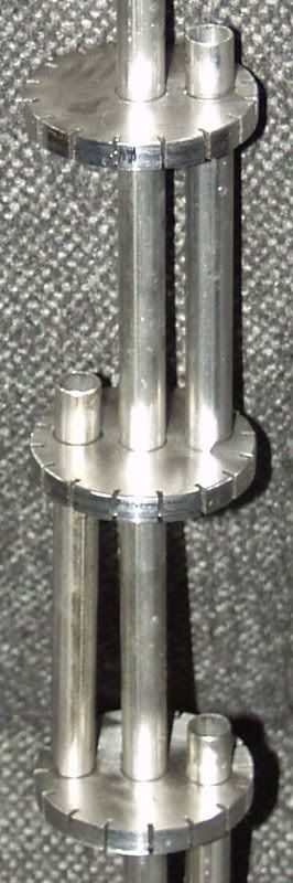
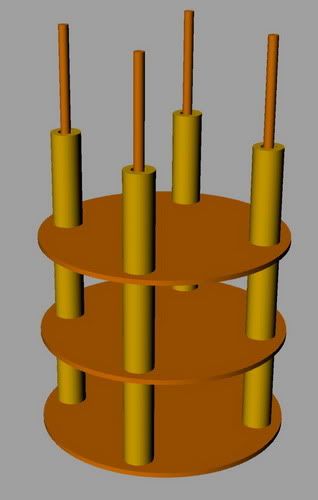
The 1/2" pieces were placed over the 3/8" pieces of tubing already welded to the disc. The 1/2" pieces were then tacked to the disc w/ a gap at the bottom. I then cut (12) pieces of 2" tubing 5.5" long. Each disc was set on a piece of 2" tubing then welded into place. The 12 sections were welded together to form a column w/ 12 plates. The inside looks somewhat like this:
Image
Image
There is a 2" female threaded coupling at the bottom. A plate was welded on the top of the column. There is a piece of 1/4"tubing welded on the side at the top to allow a thermometer. Opposite of that is a 1-1/4" tubing that goes to the takeoff arm.
Image
There is a "T" in the takeoff arm that is oriented down. The "T" is capped off on the bottom w/ a 1/4" piece of tubing welded in. This is for reflux back to the column.
Image
The reflux ties in on the third plate down from the top. The takeoff then 90's down and reduces down to 1/2" tubing. A 3' section of 1-1/4" tubing was welded over the 1/2" tubing to form a liebig condenser.
Image
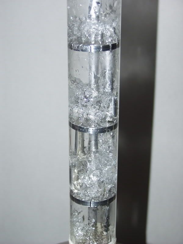
Welded a piece of 3/8" tubing and the 2" column to support the takeoff arm. All joints were tig welded. Polished her up and took her for a spin. Works pretty dang good! Still trying it out...will eventually see how hard I can run it.

I'm sure somebody is bound to mention this thing is dangerous because of the pressure that it will have to operate under in order to push the vapor up thru all that water. Well, I have 12 plates, each w/ 1.5" of water. That equates to an 18" column of water. The hydrostatic head of 18" of water is around 0.65 psi. It takes less than 1 psi for this column to operate. I have a 20 psi relief valve on the boiler. The boiler is rated at a max working pressure of 150 psi.

Next step is going to set her up to work under a vacuum. I put a 1/2" shark bite fitting on the end of the 1/2" tubing coming out of the liebig. The shark bite fitting goes to 1/2" npt. This allows me to hook up a garden hose to flush when done. I will also be able to run tubing to a vessel to catch the condensate. I will then hook up a vacuum pump to this vessel to operate the system under a vacuum. I also have plans to weld in pieces of 1/4" tubing at the top of each plate that will go to a 1/2" header that will allow me to drain each plate.

Wonder what I will get into the next time I have a month off...
User avatar
LWTCS
Site Mod
Posts: 13003
Joined: Mon Jan 26, 2009 6:04 pm
Location: Treasure Coast

Re: 2" bubble cap still

Post by LWTCS »

Can't comment on your pressure issue (or the lack there of).

But your inside column design is exactly how my in-line thumper is designed (thanks Hawke). Minus the down commers. My thumper does not flood and will drain freely should the fluid level raise.

I also employ a similar (yet different) design for my refining orb.

I'd be very interested to see how hard you can push without smearing your cuts.
I'm wondering if its stripping to much flavor? Lotsah height there. Reflux column height.

Got a name for that monster?
Last edited by LWTCS on Wed Dec 30, 2009 4:30 pm, edited 1 time in total.
Trample the injured and hurdle the dead.
User avatar
LWTCS
Site Mod
Posts: 13003
Joined: Mon Jan 26, 2009 6:04 pm
Location: Treasure Coast

Re: 2" bubble cap still

Post by LWTCS »

Did Barney's research influence this build I wonder?

Certainly did influence my refining orb re-build.
Trample the injured and hurdle the dead.
olddog
retired
Posts: 3618
Joined: Fri Jan 16, 2009 6:16 pm
Location: WEST OZ

Re: 2" bubble cap still

Post by olddog »

Looks like an adaption from a commercial type column still, or fractionating column.
Attachments
Tray_Distillation_Tower.PNG
OLD DOG LEARNING NEW TRICKS ......
rad14701
retired
Posts: 20865
Joined: Wed Dec 19, 2007 4:46 pm
Location: New York, USA

Re: 2" bubble cap still

Post by rad14701 »

I'm kinda curious about how you'll get reflux without a reflux condenser...
User avatar
LWTCS
Site Mod
Posts: 13003
Joined: Mon Jan 26, 2009 6:04 pm
Location: Treasure Coast

Re: 2" bubble cap still

Post by LWTCS »

Teenie dog dishes at every segment (i'm kidding )?

Actually, I wonder how long,, if at all it takes for the column to settle in.

Each section seems to be an in-line thumper. So I'm thinking without some kind of reflux condenser each segment would need a liquid charge of some kind prior to heat up.

Takes awhile for mine to settle in. Just prior to full on heat up, my float dances hard. Then stops and takes awhile to come back and find the soft dance.
Trample the injured and hurdle the dead.
Chasin' Tales
Novice
Posts: 30
Joined: Wed Dec 30, 2009 12:36 pm
Location: dark side of the moon

Re: 2" bubble cap still

Post by Chasin' Tales »

This still was built for producing the cleanest, purest neutral possible. I'm a vodka drinker :). Does a great job of it from what I've seen so far.

Yes, each section is like a thumper. Instead of this design I was considering just making a bunch of small thumpers with each connected w/ tubing for both vapor to flow up and liquid to flow back down. The design I went with seemed easier in my head.

Yes, I modeled this design based on research done on commercial bubble cap stills. However, most commercial columns are designed as continuous stills. While I could easily set this up to run like that, she's strictly a batch still.

No, I do not have a name for her yet. No, Barney's research did not influence this build. I like what he's doing though.

And the question about getting reflux w/o a condenser...I actually got enough air cooling that I didn't need to run the leibig. If you look in the pictures There are two needle valves below the "T" on the takeoff arm. I can send the condensed liquid back to the column to reflux. I can take the liquid off. Or, I can do a combination of the two. The first run I didn't run very hard. I was getting very little condensate down the leibig. If I opened the needle valve to takeoff at the 'T', I would get a considerable amount of condensate. I have since taken out the straight piece of pipe on the takeoff arm between the two 90's. The takeoff arm is now just fittings back to back. I still get most of the condensation by air cooling before the leibig. Because of the good amount of air cooled liquid to reflux, the column charges pretty quick. I start off running a 4500w 220v element on full power for about 20-30 minutes. The boiler is a 19 gallon water heater. Each run has been about 10 gallons. After 20-30 minutes I switch over to 110v and put a voltage controller on the element. I slowly dial the voltage controller up while monitoring temps, keeping the reflux valve open. It did a great job of separating foreshots & heads. Once it got to hearts I played with it a bit. I can shut the reflux valve and takeoff from the 'T' also and still get clean stuff. Very happy with it so far. Got to get a couple more washes going!
Dnderhead
Angel's Share
Angel's Share
Posts: 13666
Joined: Sun Dec 23, 2007 8:07 pm
Location: up north

Re: 2" bubble cap still

Post by Dnderhead »

how much diferance between metric pipe,,and US?
HookLine
retired
Posts: 5628
Joined: Sun May 13, 2007 8:38 am
Location: OzLand

Re: 2" bubble cap still

Post by HookLine »

Dnderhead wrote:how much diferance between metric pipe,,and US?
A lot of tubes/pipes and fittings didn't change actual size when we went metric. They just rounded off imperial measurement to the closest metric size. So 2" became 50 mm (actual size 50.8 mm), 3/8" became 10 mm (actual size 9.525 mm). And so on.

Most other stuff went genuinely metric, though we can still get imperial stuff too, like threads.
Be safe.
Be discreet.
And have fun.
Dnderhead
Angel's Share
Angel's Share
Posts: 13666
Joined: Sun Dec 23, 2007 8:07 pm
Location: up north

Re: 2" bubble cap still

Post by Dnderhead »

what a bummer. I was hopeing that a "cap" from one whould fit in the other.
Rufus
Novice
Posts: 16
Joined: Wed Dec 23, 2009 3:39 pm

Re: 2" bubble cap still

Post by Rufus »

I like what you've done here. Can you submit a photo of the 1/2" ID tubing placed over the 3/8" tubing that's attached to each plate?
Thanks
R
decoy
Rumrunner
Posts: 676
Joined: Fri Jan 06, 2006 4:21 pm

Re: 2" bubble cap still

Post by decoy »

These where some tests i did some time ago on a 2" plate column
the plates where 4" apart.
Image

Image

The column worked well but it was a lot of work.
Image

I figured you could simply achive the same result using discs as you have threaded or soldered on copper wire,
there was no need for the bubble caps just do lots of small hacksaw cuts around the disc.
you will need more or deeper slots or cuts around the disc at the base of the column and less as you go up the column, you can simply increase the cut as you test it.
the down comers will prevent the plates from flooding you dont need to do the J just drop it to the bottom of the next plate with a noch at the bottom for the airlock
Image

hope it gives you some ideas to simplify what you are doing.
CoOkEd
Novice
Posts: 43
Joined: Mon Dec 07, 2009 9:25 am

Re: 2" bubble cap still

Post by CoOkEd »

Decoy, does the vapor flow up through the hack saw cuts and liquid down through the tubes with the center tube not doing anything?
decoy
Rumrunner
Posts: 676
Joined: Fri Jan 06, 2006 4:21 pm

Re: 2" bubble cap still

Post by decoy »

you are correct..
Rufus
Novice
Posts: 16
Joined: Wed Dec 23, 2009 3:39 pm

Re: 2" bubble cap still

Post by Rufus »

Decoy, is the center tube there to manintain the space between trays? What type of metal did you use for the downcomers and trays? Thank you both for the photos they both provides me with lots of ideas. Finally where'd you get the glass column?
decoy
Rumrunner
Posts: 676
Joined: Fri Jan 06, 2006 4:21 pm

Re: 2" bubble cap still

Post by decoy »

its all Stainless
the centre tube did 2 jobs one was to space the plates and the i had a strip of circuit board going down the length of the centre tube with temp sensors spaced to measure the temp at different level of the column.

so you dont need to use a centre tube if you dont want to.

look for a laboratory glass blowing place or just glass blowing place would point you to someone
a 2" 1.5m long 3mm wall tube was $80 Au.
adama_bill
Novice
Posts: 60
Joined: Mon Mar 23, 2009 12:25 am
Location: OzLand - South

Re: 2" bubble cap still

Post by adama_bill »

Decoy

I LOVE YOUR WORK!
ballbuster
Novice
Posts: 5
Joined: Thu Feb 18, 2010 1:25 pm

Re: 2" bubble cap still

Post by ballbuster »

Can we all see a pic or 2, or more, of the pretty SS and glass quad-plated, vapor slotted with opposed downcomers, complete with dualtasking plate spacing, full digital temp sensing at each plate level center tube. oh Plz Pretty Plz thanks BallBuster
Kerry
Novice
Posts: 19
Joined: Fri Jan 28, 2011 10:58 pm

Re: 2" bubble cap still

Post by Kerry »

Hello CT,

What sort of production rates are you getting out of this column?

I am a bit confused how you are getting reflux... and I know you said there was enough air cooling to cause it... without a cooler of some sort. But, I am wondering how is the vapour mix from above the third plate isn't passing into the reflux catchment as there isn't an upside down 'sink catchment' and even if it did have that, wouldn't that reflux catchment need to be pre-filled with liquid? Also, i may be completely wrong, in my observation, but I would like to know how that works. I would also like to know why the third from the top plate was chosen (to save energy?).

Also, hypothetically, if this was to be converted to a continuous operation, what would need to be done?

BTW, it looks very neat!

Thank you.
Post Reply