Its either a 1' or 1 1/4" female pipe thread x copper adapter
Drilled the hole just big enough to side the adapter in. The fitting has a shoulder and the soldered it using "sure-clean" its a liquid flux works like a charm.
Heating Element Control
Moderator: Site Moderator
-
still crazy
- Rumrunner
- Posts: 706
- Joined: Wed Feb 03, 2010 6:11 am
Re: Heating Element Control
Daddy used, to say " Any landing you can walk away from is a good one"
Calculations don't mean shit when compared to the real world practical experience of many...RAD 9/2010
Calculations don't mean shit when compared to the real world practical experience of many...RAD 9/2010
-
radiatorboy
- Novice
- Posts: 46
- Joined: Fri Jul 24, 2009 2:40 am
- Location: south coast of nsw
Re: Heating Element Control
i'm thinking about making a controler for my boiler have a 3200w for fast boil up and a 1800w for running in reflux mode. but what to control this one so i can use it in pot mode. i was think about pinto's but whats the part numbers in where to get them in aus.
GO THE BUNNYS
-
MuleKicker
- retired
- Posts: 3111
- Joined: Sun Jun 14, 2009 2:14 pm
- Location: If I told you, I'd have to Kill You.
Re: Heating Element Control
Check out the new distiller lounge We have some new topics on heat control you may find helpful.
-Control Freak-
AKA MulekickerHDbrownNose
AKA MulekickerHDbrownNose
Re: Heating Element Control
If anyone is interested:
I have an idea of how to very very cheaply make a high power controller that is voltage independent (120vac or 240vac), doesn't use any active electronic components (TRIAC, SCR, etc), causes NO interference (like a varac), pure sine wave output at all times, doesn't need heatsinking, VERY robust (should last forever), SIMPLE circuit, a revamp of some OLD almost forgotten technology called saturatable reactors.
The idea involves rewinding the primary side of a discarded microwave transformer and using a POT and a ac adapter (aka wall wort) to control the power through the "saturatable reactor" (rewound microwave Xformer)
I can pursue this idea if there is any interest and create a prototype...
Everything should be as simple as possible, but no simpler.
-
still crazy
- Rumrunner
- Posts: 706
- Joined: Wed Feb 03, 2010 6:11 am
Re: Heating Element Control
Went and checked it and it is a 1" female x 1" copper pipe adapter.Kentucky shinner wrote:what is the thread size of the coupling you used to screw the element into...?
Daddy used, to say " Any landing you can walk away from is a good one"
Calculations don't mean shit when compared to the real world practical experience of many...RAD 9/2010
Calculations don't mean shit when compared to the real world practical experience of many...RAD 9/2010
Re: Heating Element Control
I finally had enough of my triac controller being too sensitive and tried various resistors on the pot to not much avail.
After using a clamp on ammeter I found that there is a big jump from around 10 amps to 15 amps and it seems best running is right in there somewhere.
Time to get that psr25 up and running.
So after ordering two 250 k pots from different places and getting the same pot with not stem to attach a knob to i looked in a local electronics supply house and viola there it was and cheaper than online
I ordered a ssr heatsink off of ebay but got tired of waiting for it so I drilled and tapped a cpu heatsink. Attached a 12v fan and found a wal wart that put out 12v and test ran it for a few minutes.
It is totally linear and just in the five minutes it ran it way cooler. I couldn't even feel the aluminum heatsink get warm which worried me somewhat but I have good contact with the heatsink and thermal paste between them.
The triac might work better for 110v but for 220 I think this psr25 is going to be the way to go.
Re: Heating Element Control
@still crazy
I have had a chance to test the controller design posted by Centar, at least partially, and here are my findings...
Today I dug out two small clear LED's of unknown specifications and soldered them to a printed circuit board I had kicking around, with opposing polarity... I then fed the LED's with the output of my high power TRIAC (MT2), running through both an 820 Ohm and a 1200 Ohm resistor (separate tests), because they were the closest values I had on hand at my immediate disposal... The output from the LED's was then fed into my dimmer switch which was already in place from the controllers original design using a 75 Ohm 25 Watt ceramic resistor... So, essentially, I replaced the ceramic resistor with the two LED's and a 1/4 Watt resistor...
Here are my findings...
The mains voltage at the time of testing was 122.5 volts...
Both resistors yielded virtually the exact same control results...
Because I didn't modify the dimmer switch to come on earlier the controller doesn't kick on until the dimmer is receiving 32 volts which is how the high powered TRIAC works anyway...
After the controller was producing power I was then able to reduce the voltage to just under 2 volts before the controller stopped producing power...
On the high end I was only able to reach a reading of ~106.5 volts...
The LED's and resistor remained cool throughout the testing process...
The LED's glowed a dim red all during testing... Like I said, I have no clue what rating they are...
The LED's and resistor do work well as a power limiting circuit to the dimmer to protect the power reaching the GATE of the high power TRIAC...
The size of the resistor feeding the LED's is not overly critical as has been proven by using 820 and 1200 Ohm resistors... "Close Enough" seems to work...
I'd suggest installing a bypass switch so straight mains power can be delivered to the element during initial warm up...
Now, it should be noted that my tests only lasted a few minutes each but I highly doubt that there would be any problem in performing a complete run with the controller as it is presently configured... We'll see just as soon as I get my next wash, which I haven't started yet, is ready to run...
@Centar
Thanks for suggesting such a simple solution for a 120 volt controller... I probably won't bother switching mine back to using the 75 Ohm 25 Watt resistor at this point...
Re: Heating Element Control
Yup, aka Magnetic Amplifier.Centar wrote:If anyone is interested:
I have an idea of how to very very cheaply make a high power controller that is voltage independent (120vac or 240vac), doesn't use any active electronic components (TRIAC, SCR, etc), causes NO interference (like a varac), pure sine wave output at all times, doesn't need heatsinking, VERY robust (should last forever), SIMPLE circuit, a revamp of some OLD almost forgotten technology called saturatable reactors.
The idea involves rewinding the primary side of a discarded microwave transformer and using a POT and a ac adapter (aka wall wort) to control the power through the "saturatable reactor" (rewound microwave Xformer)
I can pursue this idea if there is any interest and create a prototype...
I had forgotten about that.
But I think that you want to rewind the SECONDARY side since your PRIMARY would be the DC Control Winding, no?
Certainly an interesting project !
Keep us posted.
squidd
Re: Heating Element Control
Squidd, I would leave the high voltage secondary winding on the xformer as it is many turns of a small gauge wire and would create the saturating flux in the xformer quite easy with a small current through it. It will be DC running through the "control" winding and as such we need some resistance to keep the current down...
Then I would completely cut off the primary (easy to do with a grinder and cut off wheel) and wind 2 coils on ether side of the center of the E core in series but opposing phase of a heavy gauge wire.
These windings would be put in series with a heater element like a dimmer and be controlled with a small pot of say a few hundred ohms to say 1k i feel (subject to experimentation) to control the power from an ac adapter of say 12vdc at say 500 ma (1/2 amp) .
These are only ball park "feeling" amounts to get started in a test model.....but i am sure it could be made to work awesome!
It would be super heavy duty and super clean output (zero interference)
and yes it could be classed as a magnetic amplifier (mag amp) but that term is usually reserved for a circuit of saturatable reactors working together to amplify a input signal.
I have been looking for a problem for this solution for a long time and heating element control seems the perfect application!...
(I actually have over 20 microwave oven transformers (MOTs) waiting for a good application)
FOR an excellent demonstration of this principal see: http://sparkbangbuzz.com/mag-amp/mag-amp.htm" onclick="window.open(this.href);return false;" rel="nofollow
RAD has "seen the light"! , excellent test you conducted there, I originally used a 5 k pot to determine the nominal value of 1k, but you are right the amount of resistance isn't critical...
You have noticed the dimness of the LEDs thus my use of bright white ones...
These LEDs should be mounted where you can see them as they also serve a few purposes:
1. an On light
2. a troubleshooting guide (if your all plugged in and no light the heater element is burned out)
3. a indication of control (as they dim even more at the highest setting) showing that the dimmer is actually changing the power.
You have also noticed that dimmers don't get to 100% power and your suggestion as well as mine is to put a bypass switch across the power TRIAC for 100% power this also stops the TRIAC from dissipating any heat as it would do mostly at the highest setting. (2 birds with 1 rock)
I have implemented this switch in my prototype (almost finished for pics!) it will be marked "ADJ" and "FULL" i think...
Then I would completely cut off the primary (easy to do with a grinder and cut off wheel) and wind 2 coils on ether side of the center of the E core in series but opposing phase of a heavy gauge wire.
These windings would be put in series with a heater element like a dimmer and be controlled with a small pot of say a few hundred ohms to say 1k i feel (subject to experimentation) to control the power from an ac adapter of say 12vdc at say 500 ma (1/2 amp) .
These are only ball park "feeling" amounts to get started in a test model.....but i am sure it could be made to work awesome!
It would be super heavy duty and super clean output (zero interference)
and yes it could be classed as a magnetic amplifier (mag amp) but that term is usually reserved for a circuit of saturatable reactors working together to amplify a input signal.
I have been looking for a problem for this solution for a long time and heating element control seems the perfect application!...
(I actually have over 20 microwave oven transformers (MOTs) waiting for a good application)
FOR an excellent demonstration of this principal see: http://sparkbangbuzz.com/mag-amp/mag-amp.htm" onclick="window.open(this.href);return false;" rel="nofollow
RAD has "seen the light"!
You have noticed the dimness of the LEDs thus my use of bright white ones...
These LEDs should be mounted where you can see them as they also serve a few purposes:
1. an On light
2. a troubleshooting guide (if your all plugged in and no light the heater element is burned out)
3. a indication of control (as they dim even more at the highest setting) showing that the dimmer is actually changing the power.
You have also noticed that dimmers don't get to 100% power and your suggestion as well as mine is to put a bypass switch across the power TRIAC for 100% power this also stops the TRIAC from dissipating any heat as it would do mostly at the highest setting. (2 birds with 1 rock)
I have implemented this switch in my prototype (almost finished for pics!) it will be marked "ADJ" and "FULL" i think...
Everything should be as simple as possible, but no simpler.
Re: Heating Element Control
The concept of saturable reactors might be better served in a topic of its own... I think it would be beyond the scope of expertise for a majority of people here and, to do it correctly, would require test equipment that few would possess unless they have experience in the electronics field...
WARNING
Tearing into appliances that have large transformers is dangerous, and can be deadly, if you don't know what you are doing... You can quite literally blow off a finger or be killed if you accidentally discharge one of the large capacitors in such appliances and some of these capacitors can hold a lethal charge for years... The same dangers are present when trying to scrap out a TRIAC from a microwave oven... Anyone attempting this should be very very careful... I have, quite literally, seen a screwdriver tip and shaft vaporized by capacitor discharge so one can only imagine what that energy would do to human flesh...
Considering how we make every attempt to promote safety here in these forums I felt that it was necessary to give fair warning about saturable reactors...
Re: Heating Element Control
Centar, would it not be possible to construct a controller that doesn't use a dimmer with LED's...??? I'm sure you've seen schematics of dimmers that use zeon lights or shockley diodes (not Schottky) in place of a DIAC... I have actually been pondering such a controller, using shockley diodes, but LED's might achieve the same goal - but perhaps not... The only issue with such a circuit is that the individual components would probably cost more than an inexpensive dimmer, considering how the potentiometer alone could cost more...
As for the Resistor + LED's + dimmer controller, I was also going to experiment using a 5K pot but decided to just swap out resistors... I'm planning on doing another test build of that controller so I may do some experimentation then...
As for the Resistor + LED's + dimmer controller, I was also going to experiment using a 5K pot but decided to just swap out resistors... I'm planning on doing another test build of that controller so I may do some experimentation then...
Re: Heating Element Control
RAD, the LEDs are NOT needed, they are only there for an indicator light, you only need the 1k 1/4 watt resister.
The DIAC function is being provided by the 600 watt dimmer as it TRIAC usually has an internal DIAC.
Neon, not Zeon are the bulbs that were once used as the DIAC in dimmers as they have a breakdown voltage of 70 volts. Zeon are "flash bulbs" used in camera flashes and strobe lights.
Tearing apart a microwave is less dangerous than playing with 240 VAC and "complicated" TRIAC circuits.
The High voltage caps in microwave ovens have an internal bleeder resister in them (but to be sure just temporarily short the cap's terminals with a screwdriver, I always do now....)
I have only come across 1 High Voltage cap in a microwave oven in my life (an industrial version) that did not have this bleeder resister and it was marked with a warning label (I didn't take note and it arced to the tool in my right hand and my left was on the chassis, BAM, right through the chest, saw the flash, felt the "2x4" across the chest, less of a shock than a tazer though...)
After uncountable electrical shocks in my life time I can attest that you need a really good jolt to kill ya, like say connecting your body to the 240 VAC line that many here are playing with.
I will make a prototype of a saturatable reactor to show how it would be simpler, cheaper, and easier than a TRIAC based controller. Then the "experimentation" part will have been done and people can just copy the design.
It will only be 3 parts:
1. an ac adapter
2. a Potentiometer (POT)
3. a partially rewound microwave oven transformer
Everything should be as simple as possible, but no simpler.
Re: Heating Element Control
Hi Centar,Centar wrote:Squidd, I would leave the high voltage secondary winding on the xformer as it is many turns of a small gauge wire and would create the saturating flux in the xformer quite easy with a small current through it. It will be DC running through the "control" winding and as such we need some resistance to keep the current down...
Then I would completely cut off the primary (easy to do with a grinder and cut off wheel) and wind 2 coils on ether side of the center of the E core in series but opposing phase of a heavy gauge wire.
These windings would be put in series with a heater element like a dimmer and be controlled with a small pot of say a few hundred ohms to say 1k i feel (subject to experimentation) to control the power from an ac adapter of say 12vdc at say 500 ma (1/2 amp) .
These are only ball park "feeling" amounts to get started in a test model.....but i am sure it could be made to work awesome!
It would be super heavy duty and super clean output (zero interference)
and yes it could be classed as a magnetic amplifier (mag amp) but that term is usually reserved for a circuit of saturatable reactors working together to amplify a input signal.
I have been looking for a problem for this solution for a long time and heating element control seems the perfect application!...
(I actually have over 20 microwave oven transformers (MOTs) waiting for a good application)
FOR an excellent demonstration of this principal see: http://sparkbangbuzz.com/mag-amp/mag-amp.htm.." onclick="window.open(this.href);return false;" rel="nofollow.
...
As you know, the secondary windings take up a lot more physical space on the core than the primary ones.
So if you remove the primary, you won't create enough space for your new windings.
What wire size are you planning on using, 12 gauge ?
Also, you have to remove the magnetic shunts.
squidd
Re: Heating Element Control
That's the one... Wrong "*eon"... I haven't tried the circuit without the LED's as yet... I made another Resistor + LED's circuit today but I think the used LED's were already fried as the controller never fired up...Centar wrote:RAD, the LEDs are NOT needed, they are only there for an indicator light, you only need the 1k 1/4 watt resister.
The DIAC function is being provided by the 600 watt dimmer as it TRIAC usually has an internal DIAC.
Neon, not Zeon are the bulbs that were once used as the DIAC in dimmers as they have a breakdown voltage of 70 volts. Zeon are "flash bulbs" used in camera flashes and strobe lights.
Yes, most modern dimmers use a Quadrac which, as you know, is a TRIAC with an internal DIAC...
Still had to interject a warning... You and I may dabble in electronics on a regular basis, but for some folks such attempts may be their first and they may not have a proper respect for the hazards yet... Some folks only live long enough to make one mistake...Centar wrote:Tearing apart a microwave is less dangerous than playing with 240 VAC and "complicated" TRIAC circuits.
The High voltage caps in microwave ovens have an internal bleeder resister in them (but to be sure just temporarily short the cap's terminals with a screwdriver, I always do now....)
<--SNIP-->
Will be interesting to see...Centar wrote:I will make a prototype of a saturatable reactor to show how it would be simpler, cheaper, and easier than a TRIAC based controller. Then the "experimentation" part will have been done and people can just copy the design.
It will only be 3 parts:
1. an ac adapter
2. a Potentiometer (POT)
3. a partially rewound microwave oven transformer
-
MuleKicker
- retired
- Posts: 3111
- Joined: Sun Jun 14, 2009 2:14 pm
- Location: If I told you, I'd have to Kill You.
Re: Heating Element Control
deffinately interesting. i remember disecting and rewinding microwave transformers in hischool to create a battery charger. it was dirty, and the primary coil (which you propose, needs to be rewound) is under the secondary. which is many windings of very small wire. Most of which is copper wire dipped in varnish. when unwound (especially from an old micro transformer) it cracks the insulation rendering it useless. Take some pics of the build. I am interested in this process, as it seems you know what yer talkin bout.Centar wrote:If anyone is interested:
I have an idea of how to very very cheaply make a high power controller that is voltage independent (120vac or 240vac), doesn't use any active electronic components (TRIAC, SCR, etc), causes NO interference (like a varac), pure sine wave output at all times, doesn't need heatsinking, VERY robust (should last forever), SIMPLE circuit, a revamp of some OLD almost forgotten technology called saturatable reactors.
The idea involves rewinding the primary side of a discarded microwave transformer and using a POT and a ac adapter (aka wall wort) to control the power through the "saturatable reactor" (rewound microwave Xformer)
I can pursue this idea if there is any interest and create a prototype...
-Control Freak-
AKA MulekickerHDbrownNose
AKA MulekickerHDbrownNose
Re: Heating Element Control
Mulekicker, the cleanest and easiest way to remove the windings from a microwave transformer (although destructively) is to use a grinder with a cut off wheel to cut the ends of the windings off and then use a hammer and punch to drive out the left over wire in the core. I have done quite a few transformer rewinds and have found this the fastest method.
Trying to keep the wire from the transformer is almost useless as you have seen what happens to the shellac/enamel insulation on it when unwound, let along trying to straighten it out again.
Use NEW wire to rewind with. Any kind will work as long as it insulated.
Ya MOT's are good for battery chargers, arc and spot welders, tesla coils, jacobs ladders, high current supplies, inverters, and now saturatable reactors for heating element control!
Everything should be as simple as possible, but no simpler.
Re: Heating Element Control
I had all the components necessary for the basic Triac build posted earlier by Odessit.

.
Everything works fine (up to a point) and control level is very good (400W+ +/- 2%) but from around 700-800 watts (using a power meter) suddenly I lose control and power jumps up to full 2200W rating of my element.
I'm using a 600V 8A Triac and power meter is reporting about 5.1A at 750W.
Triac is mounted to a heatsink with a fan and doesn't get hot and I've tried different resistor values on both the pot and resistor after.
Anyone got any suggestions where I should be looking at?
Don't have a local option for a bigger triac that has the isolated heatsink (why they make non-isolated ones???) otherwise I'd just try that before posting.
Thanks
Edit: Also would a 600V 8A Triac be able to handle more current than 8A when voltage is at 240V or does it not work like that?
2" 1.5M Old Dog copper VM with SS 1/2" ball valve and 50L keg with 2200W element + triac controller
My old CM "neutral" was like the Leningrad T-34. Rough, unrefined and often rolled straight off the production line and into battle...
My old CM "neutral" was like the Leningrad T-34. Rough, unrefined and often rolled straight off the production line and into battle...
Re: Heating Element Control
CLACKER, Hmmm lets see 8amps times 240 volts = 1920 watts MAX that your TRIAC can handle (less than that to be on the safe side)
your overloading that TRIAC....getting hot or not...
You are also experiencing the "hysteresis" of a simple TRIAC dimmer circuit. To completely remove all artifacts from operation
You would need to "line switch" the triac and also add a bridge rectifier (4 diodes) and 2 more resisters to make it work absolutly perfect (by the way this also fixs the problems that cheap dimmer have with inductive loads)
I have attached a schematic of the "ULTIMATE" dimmer circuit to put an end to the "dimmer research"
This dimmer circuit will dim all inductive loads, has no hysteresis, very smooth control, and is unaffected by load.
The final power handling ability will be determined by the power TRIAC used.
Please note that D1 and Q2 are usually combined into one device these days in most 300 and 600 watt dimmers...
Replace Q1 with a TRIAC of suitable current handling
C2 and L1 are not needed only there to help clean up noise.
- Attachments
-
- dimmer2.gif (9.37 KiB) Viewed 5453 times
Everything should be as simple as possible, but no simpler.
Re: Heating Element Control
Thanks Centar for the prompt response. I made a dumb assumption that 240V would mean able to handle more current than at 600V.
Ducked over and grabbed a 16A 400V Triac that turned out to be Isolated! Was very happy as it was a 5 min swap and she looks stable at 900W now!
I'll put up some pics next day or so.
Thanks again; I'm interested in your circuit as well as I could make use of a power controller for induction loads.
Ducked over and grabbed a 16A 400V Triac that turned out to be Isolated! Was very happy as it was a 5 min swap and she looks stable at 900W now!
I'll put up some pics next day or so.
Thanks again; I'm interested in your circuit as well as I could make use of a power controller for induction loads.
2" 1.5M Old Dog copper VM with SS 1/2" ball valve and 50L keg with 2200W element + triac controller
My old CM "neutral" was like the Leningrad T-34. Rough, unrefined and often rolled straight off the production line and into battle...
My old CM "neutral" was like the Leningrad T-34. Rough, unrefined and often rolled straight off the production line and into battle...
Re: Heating Element Control
I am very interested. I have been looking at switching to electric heating for quite a while now and I think I am ready to give it a go. I have an old microwave already. I have a physics degree, but nothing like the understanding that comes from 30 years of electronics experience. Would you mind sharing the basic realtionships (ballpark figures) such as number of turns, wire size, POT range, input /output power range, etc. I would like to start building one. I am happy to give you feedback and data from my construction of a controller of your design. I would like to make a controller for either a 4500W 240V element or a 2000W 120V element. I appreciate any advice you have to offer.Centar wrote:If anyone is interested:
I have an idea of how to very very cheaply make a high power controller that is voltage independent (120vac or 240vac), doesn't use any active electronic components (TRIAC, SCR, etc), causes NO interference (like a varac), pure sine wave output at all times, doesn't need heatsinking, VERY robust (should last forever), SIMPLE circuit, a revamp of some OLD almost forgotten technology called saturatable reactors.
The idea involves rewinding the primary side of a discarded microwave transformer and using a POT and a ac adapter (aka wall wort) to control the power through the "saturatable reactor" (rewound microwave Xformer)
I can pursue this idea if there is any interest and create a prototype...
Re: Heating Element Control
Centar, your "ULTIMATE" design is not the only means of building a hysteresis free controller... However, no controller will be totally hysteresis free unless the minimum power parameter is above the breakover of the components used... This design is also beyond the capabilities of most of the members who are looking for a BASIC controller that THEY can make as a DIY project... Also, most folks here can't go by schematics alone, which is why simple dimmer controllers are sought after...
I have several copies of the schematic you posted, as well as build instructions, and even several PCB layouts for it... It is a very difficult design to build without a PCB and although I haven't attempted to do so myself I have seen several sloppy attempts... I haven't posted this design because there are simpler designs which accomplish the same results for the needs of most folks looking for basic controllers and, as mentioned, is beyond the build capabilities of most of those folks... Pre-made PCB's for this design are available from several locations on the internet for roughly $12USD, which is almost more than the cost of a complete basic dimmer-based controller...
I'm not saying that this isn't a nice design, I just don't consider it to be the "ULTIMATE" controller you have professed it to be, for the reasons mentioned...
Do you have a working controller of this design so members can see an actual component view...???
Re: Heating Element Control
Rad, true what you say about the complexity...just meant "technically the best" not the easiest, have never built the circuit but it is straight forward, was more for information.
Defiantly not the easiest to build for people without experience....thus my "saturatable reactor" idea, super simple and no fiddly electronics and bulletproof.....
FREEZINGO, yup I will definitely will supply all data and personal touch with this saturatable reactor project and will try to simplify it as much as possible.....which brings me to my next point/question...It has occurred to me that cutting off the primary on most MOTs is much more difficult than the secondary (which is what I have always done) because it is located at the bottom where the mounting plate is usually welded on and there is no room to cut in.....also rewinding the transformer may intimidate alot of people, so to make things "simple" yet maybe more difficult (thus this question) I am thinking of using 2 (two) MOTs with their original windings left in place and wiring them in a "saturatable reactor" fashion. This would make building this super simple for anyone BUT REQUIRES 2 matching microwave oven trannsformers (may be more difficult for alot of people to get, Yet I have a few "sets" of matching MOTs)
Which do you think is easier? 2 matching MOTs or rewinding the hard to get at primary......still thinking.......hmmmmmmmm
Everything should be as simple as possible, but no simpler.

Re: Heating Element Control
I'm going to throw something out, at one time I had a welder, it was simply two coils primary and secondary with a "sliding" core
would something like that be used /made?
would something like that be used /made?
Re: Heating Element Control
Actually Duderhead, you read my mind...
After considerable thought and some experimentation, I have decided that the saturatable reactor from a MOT is not practical and have changed my mind for an even more simpler version of a modified microwave oven transformer, a variable inducer.
Very similar to what is used in some stick welders....(not quite sure how one would modify a welder for this purpose BUT it is an interesting option)
By removing ALL the windings on a MOT and rewinding it with 1 coil of 10 gauge wire (as much as we can get on there) we can easily create a large power inducer (choke) and wire this inline "in series" with the line power to the heating element.
This will cut the power going to the heating element considerably.
We can then reduce the inductance through mechanical means. The cores on MOTs are "E" and and "I" cores welded together.
Grinding off these 2 welds freeing the I from the E we can then devise a simple mechanical way (screw or something) to vary the magnetic coupling (the space) between these 2 pieces thus controlling the inductance - controlling the amount of AC power that will flow through the coil to the heating element.
The less coupling (more space) the less inductance and the more power passed.
This is my new direction with this idea of using a MOT for a power controller...
Everything should be as simple as possible, but no simpler.
Re: Heating Element Control
I still like the saturable reactor idea, it seems like a very robust solution. Even if it is difficult I want to give it a try. If I can get the winding done, can you still give me guidance?
Re: Heating Element Control
Freezingo, Because of the existing wire diameter/number of turns of the secondary and primary on a MOT, it is not practical as a saturatable reactor UNLESS you were to wind both a new secondary and primary for it...
If you care to learn more on this subject check out>
http://ia311013.us.archive.org/2/items/ ... ifiers.pdf" onclick="window.open(this.href);return false;" rel="nofollow
The variable inducer idea isn't much different just simpler, Only 1 coil to wind and no pots or adapters just a simple mechanical adjustment... It is the basis of a saturatable reactor...
Everything should be as simple as possible, but no simpler.
Re: Heating Element Control
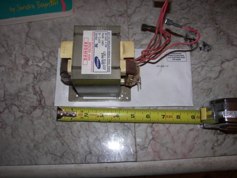
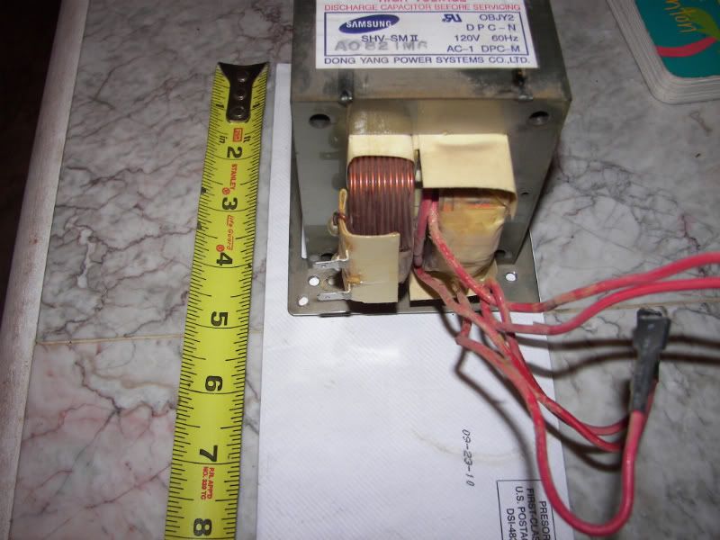
I took the MOT out of the microwave and it really doesn't look that difficult to remove the windings. I will post a picture of the MOT shortly. How many turns and what wire size (ballpark figures) need to be put on? There are 55 turns of the larger wire on the MOT now. *ADDED PICS* Do you think this could be used to control a 2000W 120V element between 750W and 2000W ? How about a 4500W 240V element between 1000W and 4500W? After reading a bit of the link you posted I get the idea that the weak point of this design would be the wire insulation (?) which I think is ok since I assume I will be using new insulated wire which probably has much better insulation than whatever is on the windings... What about using stranded wire (such as from an extension cord)? I am sure it would make winding the new coils much easier, but don't know if it is appropriate.
Re: Heating Element Control
this thread is now 42 pages long
surely there is a way to do this that is reasonably simple ?
i really want something sorted by XMAS as i am moving into a new place with a great workshop and pool for a water tank for the condenser on my new keg boka
would love to sort a power controller for it
surely there is a way to do this that is reasonably simple ?
i really want something sorted by XMAS as i am moving into a new place with a great workshop and pool for a water tank for the condenser on my new keg boka
would love to sort a power controller for it
Re: Heating Element Control
Here's my Triac based power controller from Odessit's diagram.
I'm sure my work confirms I'm an amateur but I have a healthy respect for mains and made sure *everything* is well grounded.
As you can see I originally was going for the design posted with the light dimmer but I couldn't get it working.
The power supply housing was really ideal as it had the IEC plug, power switch, fan and case ground all there and ready to go. Also used the inductor/cap suppression circuit to boot!
I haven't always followed wire colour convention.
Heatsink was from a graphics card and got an isolated triac so the heatsink connection wasn't "live". Why the hell do they make non-isolated versions anyway?
Added a 240V to 9V AC adapter to power the fan and she's nicely contained now. Sloppy pot placement meant the fan was mounted externally.
I seem to have made a simple ciruit look really complex but it was easy enough to make and apart from the $20 dimmer and $5 first Triac which was underspec'd... total cost was about $10.00. Parts sourced from Jaycar for those down here.
There is a buzz from the inductor but using a power meter output settles after a few mins and then seems pretty stable. +/- 2% I'd say at 1000watts.
I'll report back if it dies and after how many hours use.
First pic is pretty much the physical representation of the diagram from Odessit posted earlier and the second pic has the 9v adapter and noise suppression cap/inductor.
2" 1.5M Old Dog copper VM with SS 1/2" ball valve and 50L keg with 2200W element + triac controller
My old CM "neutral" was like the Leningrad T-34. Rough, unrefined and often rolled straight off the production line and into battle...
My old CM "neutral" was like the Leningrad T-34. Rough, unrefined and often rolled straight off the production line and into battle...
Re: Heating Element Control
nice one clacker
i have done one the same but it does not seem to work and will have to ask some experts what the issue is. must be something simple as it's working but does not have linear change across the pot range.
i WILL HAVE TO check my triac to male sure it's isolated !!! did not know they might be live !!!
then i need a fan and a box like yours once it's sorted.
please keep us posted on your results as they are a simple build mostly