Joints for glass columns

Vapor, Liquid or Cooling Management. Flutes, plates, etc.

Moderator: Site Moderator

Post Reply
snuffy
Swill Maker
Posts: 296
Joined: Sat Sep 13, 2008 8:21 pm

Joints for glass columns

Post by snuffy »

I just finished putting the male joints on the three pieces of glass tubing. Here are some pictures showing how it was done. A table saw, a drill press and hand tools were used to make everything. The goal here is to do everything so it can be easily and inexpensively duplicated.

Image

I built an 11 ft table by putting a door next to my 4x4 ft saw table. It was leveled with a laser so the two surfaces were co-planar. the laser level came from a liquidator and cost $6US. Then I made eight cradles out of plywood with cork lining to fit the glass tube. The glass came in 5 ft lengths and I had it cut and annealed to 4,3,2 and 1 ft. The four ft length is being held in reserve, the 3,2 and 1 with the other fittings will give a total column height as great as 9 ft.

The cradles had identical alignment targets that I made on my laser printer from CAD drawings. I lined them up one by one and fixed them to the table with adhesive tape. When I placed the glass tubing in the cradles, the laser beam (with a crosshair pattern) went right through the middle of the tubes. The symetrical pattern of the laser reflections shows the alignment is correct. Moving one of the tubes a tiny amount would wreck the symmetry.

Image

With the tubes all aligned, I inserted the joints and luted them with flour paste. The joints were aligned with each other by connecting them with a coupling and rotating the tubes in opposite directions. After the the lute hardened, I sealed the outside end with silicone. This closeup shows the joint: lute, three layers of soft cotton crochet yarn and silicone. In the background is a cradle with alignment target.

Image

The male joints are a copper coupling with a piece of pipe. The female joints are just a coupling. I polished the mating surfaces with 400 grit sandpaper, 000 steel wool and then a buffer with polishing compound. They slide in and out very smoothly. The final seal will be a strip of cork and a stainless steel band clamp. The joint is very strong.

Image

Soon I will be using the tubes to measure flow rates and back pressure of gas and water in a packed column. I'll post that when I have some results.
Time's a wasting!!!
punkin
Master of Distillation
Posts: 2711
Joined: Fri Oct 05, 2007 12:36 pm
Location: Northern NSW Oz Trail Ya

Re: Joints for glass columns

Post by punkin »

Man you impress me so much snuffy, your attention to detail is amazing. Your undestanding of the theory behind our craft is matched by few here i blieve, please keep posting and explaining what you do..


ExtremelyFukingImpressivePunkin
eternalfrost
Trainee
Posts: 785
Joined: Fri Mar 14, 2008 4:28 pm

Re: Joints for glass columns

Post by eternalfrost »

:o
decoy
Rumrunner
Posts: 676
Joined: Fri Jan 06, 2006 4:21 pm

Re: Joints for glass columns

Post by decoy »

looking good there ...

Just wondering why you didnt put the join tube outside the glass..?
also the glass tubes normaly are 1.5M long that should be enough for a column ?

regardless its looking good, keep the posts and photos comming..

cheers.
snuffy
Swill Maker
Posts: 296
Joined: Sat Sep 13, 2008 8:21 pm

Re: Joints for glass columns

Post by snuffy »

decoy wrote: Just wondering why you didnt put the join tube outside the glass..?
Glass is very strong in compression and has a small coefficient of expansion compared to copper. The lute, cotton and silicone will be compressed when the copper expands. If the copper was on the outside, there is a chance that the seals would open up under tension since the copper would get bigger than the glass and pull away.
decoy wrote: also the glass tubes normaly are 1.5M long that should be enough for a column ?
Depending on how things are hooked together, I can mix and match to make columns of any length from 1 to 9 feet. All the parts are modular and can go together in any order. I figured it was the same amount of work to build a Turing Machine for distilling as to build a single purpose-built rig to test one hypothesis. They are building blocks.

This is an early design of the modular components concept:

Image

What was actually built:

Image

VM head with butterfly valve to investigate stream splitting

Image

LM head uses upper column as reservoir.

Image

There are thermometer glands and pressure ports for measurement at most places it would be useful.
Time's a wasting!!!
decoy
Rumrunner
Posts: 676
Joined: Fri Jan 06, 2006 4:21 pm

Re: Joints for glass columns

Post by decoy »

FUK.. i take my hat off and eat it....

Punkin sums it up...

Very nice work there snuffy, i realy look forward to seeing the results of your tests...

very nice...
eternalfrost
Trainee
Posts: 785
Joined: Fri Mar 14, 2008 4:28 pm

Re: Joints for glass columns

Post by eternalfrost »

that VM butterfly valve is interesting...
if im looking at it right, the valve is in the column itself and not in the side takeoff arm?
this would allow you to run all the way to "pot still mode" of 100% takeoff which is impossible with the traditional way 8)

did you make that valve yourself? it looks like you might have... if so, that would be worth its own thread in itself, id be very interested!
punkin
Master of Distillation
Posts: 2711
Joined: Fri Oct 05, 2007 12:36 pm
Location: Northern NSW Oz Trail Ya

Re: Joints for glass columns

Post by punkin »

eternalfrost wrote:that VM butterfly valve is interesting...
if im looking at it right, the valve is in the column itself and not in the side takeoff arm?
this would allow you to run all the way to "pot still mode" of 100% takeoff which is impossible with the traditional way 8)

did you make that valve yourself? it looks like you might have... if so, that would be worth its own thread in itself, id be very interested!

Hope i get credit for the idea :idea:
HookLine
retired
Posts: 5628
Joined: Sun May 13, 2007 8:38 am
Location: OzLand

Re: Joints for glass columns

Post by HookLine »

Awesome work, snuffy. Setting a new standard.

Can't wait to see some good video of that in action.
Be safe.
Be discreet.
And have fun.
maoule
Bootlegger
Posts: 134
Joined: Sun Nov 02, 2008 9:24 am
Location: misery

Re: Joints for glass columns

Post by maoule »

punkin wrote:
eternalfrost wrote:that VM butterfly valve is interesting...
if im looking at it right, the valve is in the column itself and not in the side takeoff arm?
this would allow you to run all the way to "pot still mode" of 100% takeoff which is impossible with the traditional way 8)

did you make that valve yourself? it looks like you might have... if so, that would be worth its own thread in itself, id be very interested!

Hope i get credit for the idea :idea:
I was in on it too!!! :D
2" Bokmini, VM and potstill heads
7.75gal. & 15.5gal electric boilers
maoule
Bootlegger
Posts: 134
Joined: Sun Nov 02, 2008 9:24 am
Location: misery

Re: Joints for glass columns

Post by maoule »

Suh-WEEEEET. Pretty stuff, Snuff. I'll send you some wash to run if you ain't got any :lol: Hurry up, already...I can't wait. :!: :!:
2" Bokmini, VM and potstill heads
7.75gal. & 15.5gal electric boilers
rad14701
retired
Posts: 20865
Joined: Wed Dec 19, 2007 4:46 pm
Location: New York, USA

Re: Joints for glass columns

Post by rad14701 »

Looking good, snuffy... Great work... Looking forward to hearing how everything works... I think you'll be able to shed some real world light onto several different theories with those components...
snuffy
Swill Maker
Posts: 296
Joined: Sat Sep 13, 2008 8:21 pm

Re: Joints for glass columns

Post by snuffy »

The butterfly valve is above the vapor takeoff port (3/4 male pipe thread).

The first mention of a butterfly valve is in The Compleat Distiller:

Image

The phrasing in the text led me to believe VM had different %abv in the reflux and product vapor streams. I know now that this is NOT* true. If the force of gravity was strong enough to overcome thermal Brownian motion (like in a gas centrifuge or on Jupiter) it might be possible to send the water up and the ETOH sideways.

Priority aside, minime, punkin and Manu de Hanoi were all equally provocative in sending me in this direction.

The valve is not perfect and will not seal completely. It is pretty tight, good enough for fine-tuning the vapor balance. It might work for pot still mode with some reflux -- time will tell.

Next step is calibrating the flow through the components with the micromanometer. I'm still waiting the arrival of some glass gauge tube, but am going to try it with the vinyl tubing. I just finished coating the inside of the vinyl with a supposedly miraculous electrostatic water repellent. We'll see if that makes the walls of the tube hydrophobic enough to improve the accuracy.

Please bear in mind the test boiler will be tiny -- so I can turn runs around quickly for different measurements. This is an experimental rig, not a production one. The goal is to do the cleaning and test run by Christmas.

* edit - the NOT was missing in the original. sorry for the confusion.
Last edited by snuffy on Thu Dec 18, 2008 3:41 am, edited 1 time in total.
Time's a wasting!!!
decoy
Rumrunner
Posts: 676
Joined: Fri Jan 06, 2006 4:21 pm

Re: Joints for glass columns

Post by decoy »

Snuffy if this is going of topic let us know..
but somthing you can maybee resolve in your tests..
snuffy wrote: The phrasing in the text led me to believe VM had different %abv in the reflux and product vapor streams. I know now that this is true. If the force of gravity was strong enough to overcome thermal Brownian motion (like in a gas centrifuge or on Jupiter) it might be possible to send the water up and the ETOH sideways.
This is an interesting comment, i understood it that the benafit of a VM head was that you can control the reflux and take off % more accuratly "because the volume of vapour is greater then the condensed liquid reflux so you dont need a tiny precision valve" we know for a fact that while in liquid form that ethanol and water will both evaporate together at temp based on abv.

While the water and ethanol are in vapour state are they somehow chemicly linked or can they be seperated as stated by gravity?

my thought is that regardless of the difference in density as a result of the upward movment due to heat they would both be pushed up at same rate to reflux condensor.

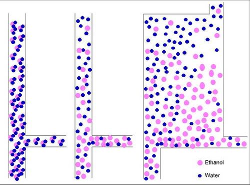
in the following examples..
Image

The first fig is my interpretation of VM head operation...

the second fig is the described operation of a vm head

the third fig is my view if the the operation is based on density of ethanol in relation to water.

in the third fig an expansion chamber is added where vapor enters the chamber on the bottom left, it travels up due to heat and the upward current is diffused and the reflux exit is at top right as the vapor travels upward and accross to right the denser ethanol drops and exits to take off at bottom right while water vapour travels upward with a lower concentration of ethanol.
snuffy
Swill Maker
Posts: 296
Joined: Sat Sep 13, 2008 8:21 pm

Re: Joints for glass columns

Post by snuffy »

This is so totally on topic. As I understand it, your figure 1 is correct and the other two are not.

What we need to do is design an experiment that will tell us what is going on. I expect to st up an LM head with reservoir above the VM takeoff. adjusting the reflux /bypass rate with the butterfly valve an the ball valve will give us control over the ratio of split streams. I hypothesize the the %abv of the two outputs will be the same %abv - though perhaps with different congeners. So that's one test.

As I understand it, a mixture of vapors will act as the average of its two components. Light molecules with have higher velocity and heavier ones sill have less. but because of the stochastic slam-dance in the mosh pit of the the isothermal container, light and heavy will have equal kinetic energy - the average mv^2 will be the same for both substances.

The result being that the mixture behaves as a homogeneous vapor with thermal energy equal to the average of the two components as determined by their relative ratio.

If the %abv of the upper and side streams is similar, then the experiment will be to capture and measure them.

Here's some build pics of the butterfly valve:

Image

The valve plate is a friction fit on the shaft. I scribed it with a compass, then cut it out roughly with tin snips and carefully filed to the scribe line from the compass. Total time: 45 minutes.

Here it is all disassembled. The tricky part was to get the two compression fittings used as shaft glands colinear on a diameter of the main body. The main body is two couplings and two pieces of pipe. The double thickness of coupling and pipe gives enough meat for tapping 1/4" NPT for the threaded fittings. I drilled the shaft hole all the way through with the bit sized for the pipe tap. Without moving anything, I swapped the drill for the tap and used the drill press as the threading tool - this keeps everything in very tight alignment. I usually spin up the drill press, turn off the motor and then engage the tap with the residual momentum to get the tap started.

Image

the hard part is flipping the tube over and reestablishing the alignment. I missed by a couple of thousandths and had to use a 1/4" chucking reamer to rebore the shaft glands to get them lined up.

Image

I tinned the strap and plate, assembled them in place inside the body and then heated with a torch to flow the solder. It took several tries to get it close. A later picture shows I was still off by about 1/32".

These views are from the bottom looking up.

Image

Image
Time's a wasting!!!
decoy
Rumrunner
Posts: 676
Joined: Fri Jan 06, 2006 4:21 pm

Re: Joints for glass columns

Post by decoy »

I may havepicked up on 1 minor problem with butterfly valve... that shouldnt be to hard to overcome if not already..

the butterfly valve is above the take off, i cant see how you will hold the head at 100% reflux to reach equilibrium for heads..

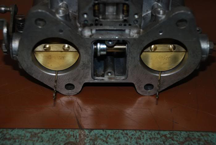
and a sugestion for the butterfly valve... :idea: have you looked at some small carburetors..

here is one of the net.. the valves are brass and you can strip the bushes for em as well, should provide a good seal..
also its a way to mount the discs to the shaft so there centred..
Image

if you have to make a valve for output..

still im thinking about some tests that could be performed

cheers..
snuffy
Swill Maker
Posts: 296
Joined: Sat Sep 13, 2008 8:21 pm

Re: Joints for glass columns

Post by snuffy »

You're reading my mind. It's snowing here and I'm stuck at home with a nasty respiratory infection, but I almost went out last night and took the carburetor off one of my neighbor's cars. It only takes about 4" to shut down the city and we've got 6", so interference by the pesky gendarmes would be minimal.

Equilibriating will be done by opening the butterfly and shutting the liquid and vapor takeoff valves. Here's a cartoon (not to scale and you'll have to imagine a butterfly valve immediately above the VM head).

Image

Once I get some numbers from various tests, we can kick around what it all means for designing production stills.

I'm still embarrassed by the missing NOT in the previous post. :oops:
Time's a wasting!!!
eternalfrost
Trainee
Posts: 785
Joined: Fri Mar 14, 2008 4:28 pm

Re: Joints for glass columns

Post by eternalfrost »

hey snuffy after looking at your valve pics and playing around for a few minutes with some sprare parts i got laying around i have a few questions...

-how does the shaft seal into the bolt on the compression fittings? at least on the spare one i have, there is a little wedge piece you have to insert into the tube that pinches the tube between itself and the bolt when you tighten it down. seems like with a solid rod staight through it would be nothing but a shaft going through a normal hole?

-do you have to loosen the bolts on the fittings to adjust it then retighten them? on the one i got when its sealed the tube cant rotate relative to the fitting, until you loosen the bolt a half a turn.

these problems might be just because im playing with an old 1/4" needle valve w/ compression fittings...
just trying to wrap my head around it because i would love to make something similar

EDIT
-------------------------------------------------
i just found these type of fittings on mcmaster. they have the wedge clip on the outside as a ring instead, so would work fine with a solid shaft. is this what you are using there?
standard_compression_s.gif
standard_compression_s.gif (3.8 KiB) Viewed 2118 times
snuffy
Swill Maker
Posts: 296
Joined: Sat Sep 13, 2008 8:21 pm

Re: Joints for glass columns

Post by snuffy »

They are ordinary 1/4" compression x 1/8" NPT. I bored them out and then ran a 1/4" chucking reamer through them. The seal is soft cotton crochet yarn. 8)

It turns easily with the seals tight. I have yet to fit the protractor on the shaft. It should read to less than 1 degree, since it has a vernier scale on it.
Time's a wasting!!!
eternalfrost
Trainee
Posts: 785
Joined: Fri Mar 14, 2008 4:28 pm

Re: Joints for glass columns

Post by eternalfrost »

good deal snuffy, would never have thought of cotton seals. do you have any worries about leaks? i wouldnt think it should be a problem since the fittings by themselves are nearly airtight by friction without even screwing the nut on.

one idea i have though is that the second fitting on the opposite side seems superfluous. a solid 1/4" hardened copper or stainless rod should be plenty beefy enough to hold the plate on a cantilever. since you have to bore out the seat anyways like you said to get the rod through there will be nearly an inch that the rod is fully supported so shouldnt be any worries about it getting out of line.
8239K150L.GIF
8239K150L.GIF (46.13 KiB) Viewed 2052 times
would sure make fabrication a snap not having to mess with alignment.

also, just to be clear, you are using this butterfly valve simply to test the effects of 'stream splitting' right? as in what difference, if any, the 'inverted funnel' theory for channeling vapor into the take off arm has? you will still have a ball valve on your take off arm to controll the takeoff like a normal VM right?
snuffy
Swill Maker
Posts: 296
Joined: Sat Sep 13, 2008 8:21 pm

Re: Joints for glass columns

Post by snuffy »

The hard part of aligning the two compression fittings was tapping the second hole. Since pipe taps are tapered, I had to flip the tube over after tapping the first side. I suppose I should have chucked the drill back in the press and used that as an alignment tool. Instead, I eyeballed it and got a tiny bit off. I ran the 1/4" brass tube through both fittings when I soldered them to the main coupling, but it moved out of alignment because of heat expansion or something. The tube was aligned before silver soldering and wasn't afterwards. That was when I had to run the reamer through. The shaft sticks out on the far side so I can attach the protractor to measure the setting of the butterfly plate.

The VM port will have a 3/4" stainless ball valve. I didn't want to pay out for a gate valve. It may be that butterfly valves will work in both legs. I'm hoping that a differential pressure manometer will allow accurately measuring the takeoff/reflux rate. Time will tell.

I just got back from the hardware store with the parts needed to attach the protractor. Tomorrow, the glass gauge tubes should arrive so I can get more precise readings on the micromanometer. The vinyl tubing is too rough on the inside and "hangs up" the water so it moves in fits and starts.

It just occurred to me that the coupling and band clamp joint would work very well for making modular copper columns. Same principle, but just solder the coupling to the pipe. Much cheaper than threaded pipe adapters. I'll have pictures when I get the first ones done.

So much to do, so little time....

---

edit - PS

I missed answering the last part of your question:

I'm hoping to use the butterfly valve to fine tune the vapor balance between the upper column and the takeoff. I haven't seen any explanation as to why the inverted elbow works -- I think it may be because it acts like an orifice plate for the connection to the upper column. I'm puzzled by minime's experience with putting a deflector plate in above the vapor takeoff.

There is a good chance that what people are calling stream splitting doesn't work the way it's imagined. I strongly suspect that the pressure that forces the vapor out the takeoff is NOT - repeat NOT - being driven by the upward flow from the boiler. The reason for this is that by Bernoulli's law, gas (or vapor) in motion exerts LESS pressure that static. So if the flow upwards was driving the pressure out the takeoff, it would be the exact opposite of Bernoulli -- which says that the upward flow should cause a pressure drop in the side leg.

So if stream-splitting is driven by upwards flow, the butterfly valve may have a paradoxical effect on the takeoff rate. This could be the explanation for why minime got the puzzling results when he added the plate above the takeoff. If he hadn't reported that result, I wouldn't have started thinking about putting in a butterfly valve.

I know this is controversial -- and is all logic and argumentation instead of reproducible measurement -- but I think the pressure that moves the vapor out to the product condenser results from the weight of the heavier-than-air vapor ABOVE the takeoff. If this is so, then a taller column above the takeoff will increase the pressure in the side arm leading to the product condenser. I'll be quite happy to prove myself wrong about this if it leads to understanding what is really happening.

Like the old boys said: Nullus in verbum.
Last edited by snuffy on Thu Dec 18, 2008 7:17 pm, edited 1 time in total.
Time's a wasting!!!
eternalfrost
Trainee
Posts: 785
Joined: Fri Mar 14, 2008 4:28 pm

Re: Joints for glass columns

Post by eternalfrost »

great info snuffy, i am unhappy with the performance of my LM and am in the process of converting it to a LM. i plan on basically chpoing out the spant plate section and replacing it with a LM arm. when all is said and done i should be able to switch back and forth between the two.

eagerly awaiting your results, im off to vacation now for the next month or so. wont be able to work on anything but will be checking in online :wink:
Post Reply