Let me explain each circuit in a little better detail.
--------------
First Circuit
The first circuit is a typical light dimmer which we can buy for a small price. First allow me to point out the dashed components are there for florescent lamps and transformer operated lamps such as low voltage halogens. If you are building this type of circuit, leave out the optional components, because they have no effect.
The triac is a special type of switch, designed to operate on AC. If you put the power terminal in series with a load (heater element, light, etc.) it is effectively an open circuit. If you connect the gate terminal to the top lead of the triac (MT2), it will come on with full current flow. Of course this is not much use to us.
In the first circuit of the three, there is a capacitor connected to a diac. A diac works like a pair of diodes connected in parallel. These diodes are special though. Their turn on voltage is usually very high, in the range of 10 to 30 volts. If you connect the diac to the MT2 leg of the triac and the other side of the diac to the gate, the triac will turn on. This doesn't help much either.
Let’s return to the capacitor. If a capacitor and a resistor are connected in series, across a DC power source, the capacitor will slowly (compared to a short circuit) charge to the supply voltage. Changing the value of the resistor will change the speed the capacitor charges.
In the circuit for the light dimmer there is a special thing going on. Since we are dealing with an AC signal, we have to look at things from a starting point and I will start with the voltage at 0 and rising for the first half of the cycle.
If we watched the voltage across the capacitor, it will start climbing, following the rising voltage of the ac signal. When the voltage, across the capacitor, reaches the breakover voltage of the diac, the diac will trigger the triac. The triac will stay on, all by itself, for the rest of the positive part of the cycle. The voltage across the triac, and therefore the rest of the circuit drops to nearly zero volts with the voltage being dropped across the load instead. This discharges the capacitor. When the voltage on the circuit crosses zero, heading for the negative part of the cycle, the triac goes off.
The negative voltage starts charging the capacitor. When the capacitor voltage goes negative enough, it turns on the diac, triggering the triac, and again the capacitor gets discharged but the triac stays on until it crosses zero again.
Let’s consider the resistor part. The resistor controls how fast the capacitor voltage follows the line voltage. A large resistance, slow charging capacitor, will cause the turn on time of the diac to lag the supply voltage and only trigger the triac late in the cycle. Smaller resistances allow the trigger earlier in the cycle, larger resistances for later in the cycle.
We can adjust the turn-on time by varying the resistance from high to low. A large enough resistance keeps the device from coming on. A small enough resistance allows it to be on all the time. A resistance in between, allows the device to be on part of the time.
Since the loads we deal with are slow to react to voltage changes, they behave with parts of cycles as if it were a reduction in supply voltage.
-----------------------
Second Circuit.
The second circuit is just a snippet of a circuit and shows that a sensitive triac, like the one in our light dimmer, can be used to trigger a power triac. The reason this is important is because of the more current a triac can handle, typically the more current it takes to turn it on. In the case of a 40 amp triac, it could take as much as 4 amps to trigger it. A variable resistor, capacitor combo can't deliver that kind of current. The other important part of that snippet is the note which explains that the resistor has to be calculated to make sure the gate current of the power triac is not exceeded.
------------------------
Third Circuit.
This is a simple switch circuit. Realizing that the resistor in this circuit is the same as the resistor in the second circuit is the important part of this diagram. The equation shows how to calculate the value for the current limiting resistor. The resistor in this circuit is the same as the resistor in the second circuit.
------------------------
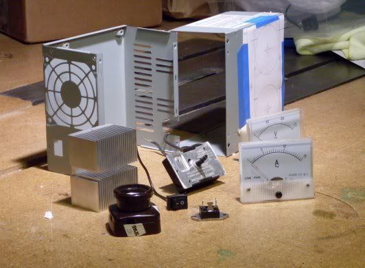
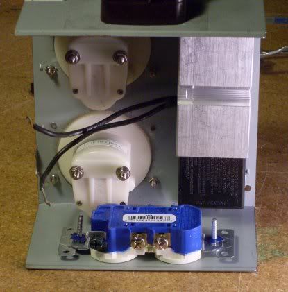
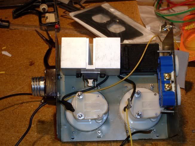
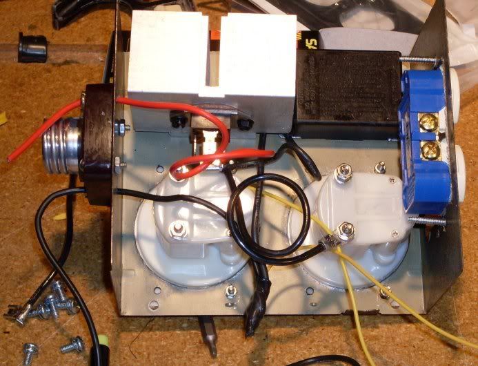
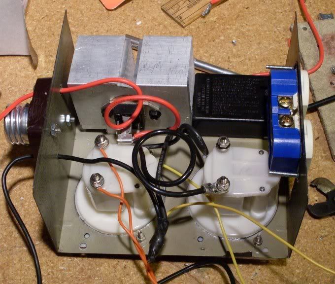
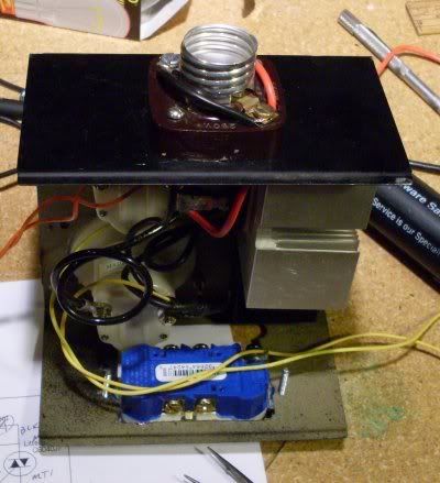
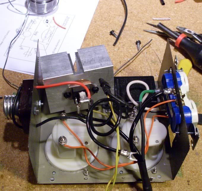
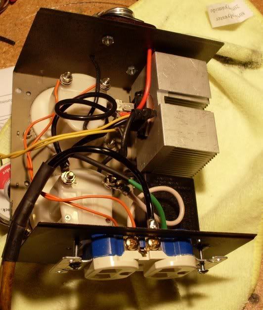
The whole story, (the first diagram I posted)
1. Start by mounting a power triac and the big resistor on a heat sink.
2. Connect one side of the resistor to MT2 of the power triac.
3. Connect the other side of the resistor to a dimmer.
4. Connect the output of the dimmer to the gate of the power triac.
5. Connect the MT1 terminal of the triac to the neutral side of the line.
6. Connect MT2 to the heating element.
7. Connect the heating element to the line voltage.

- Triac.jpg (7.76 KiB) Viewed 18177 times