Because of the large mass of the heater element and the liquid, I see no need for the speed of phase angle control in this type of heating application. Also phase angle firing produces a lot of electrical noise. The plan was to come up with a time base power control. This involves a set time frame that the power will turn on a percentage of this base time. For example, if I have a 2 second time base and wanted 50% power the power would turn on 100% for 1 second and off for one second. At 25% power setting, the power would turn on for 1/2 second and off for 1-1/2 seconds. I also wanted to get 0% to 100% control. I didn't know if I could get this but I was going to try.
The 555 timer IC output can drive up to 200ma so driving the SSR input (10ma @12v)directly from the chip output is possible. Also the 555 will work from 5v to 15v DC and the SSR has a must turn-on voltage of 3v so again a great fit. A good primer for the chip can be found at:
http://en.wikipedia.org/wiki/555_timer_IC" onclick="window.open(this.href);return false;" rel="nofollow
I modeled the circuit using LTSpice.
" LTspice®IV is a high performance Spice III simulator, schematic capture and waveform viewer with enhancements and models for easing the simulation of switching regulators. Our enhancements to Spice have made simulating switching regulators extremely fast compared to normal Spice simulators, allowing the user to view waveforms for most switching regulators in just a few minutes. Included in this download are Spice, Macro Models for 80% of Linear Technology's switching regulators, over 200 op amp models, as well as resistors, transistors and MOSFET models."
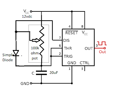
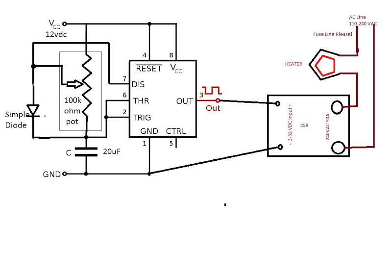
I started with the astable circuit below and modeled it into LTSpice.

By changing the resistor values I could change the duty cycle (how long on to off) but could not get below 50% on. I added the diode across the one side of R2 and all worked. By keeping total resistance 100K ohms and changing R1 and R2 I could get any %on I wanted. The 20uF cap and the total resistance controls the time base. With the 100k ohm of resistors and 20uF gives a time base of 1.3 seconds, 10uf with the same pot will give a duty cycle of about .7 seconds. I then replaced R1 and R2 with a 100k ohm pot. The balance( wiper position) of the pot resistance controls percent on to off.
I mocked up the circuit using a bread board and some spare parts. I placed a resistor with a LED on the output for testing. Below is the bread board mock up.
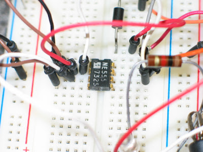
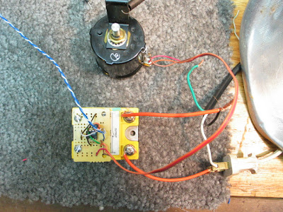
The circuit worked perfect. I measured the output with a Fluke meter displaying the duty cycle ( % on to % off). . The range of the circuit will go from 0 to 100% and almost infinitely variable. I then hooked up a SSR and a lamp to confirm the output of the 555 could drive the SSR. Again perfect. I then went to the local electrical supply store and got a set of new parts and a small PC board. Below is the picture of the almost completed board.
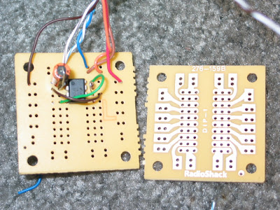
I was thinking I could mount board directly to the SSR input screws to reduce the size foot print. Drilled two holes for SSR input screws. Also I used two of the traces to get the signal to the SSR. Cut PC board smaller and mounted it.
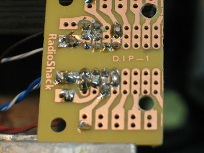
What do you know It works Great. To bad I cant solder worth shit!
So what does it cost to build? I got the PC board, cap, diode, 555, and pot for $11 USD. The SSR with shipping was $8 off Ebay. The 12vdc power supply was free, just find an old supply from 5vdc to 15vdc and don't worry about the power, the circuit doesn't draw much. To make the control feel good a 3-10 turn pot is real nice addition. A box, main power switch and some plugs and your done. A cheap easy to build power controler!
Parts List:
1 555 Timer ( note do not use low power version)
1 100k ohm linier pot ( liner, not log)
1 20uF electrolytic cap
1 simple diode
1 any 5-15vdc power supply (12vdc best)
1 SSR with 3-32VDC input and an output rating above what you would like to control
Misc plugs fuses etc.
Checking output with Fluke set to measure duty cycle ( %on to % off)! Meater at 50%. I can get any number from 0 to 100%
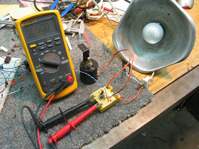
Please dont wire your test light like this!
Some more notes: Back of SSR should be mounted using heat transfer compound to something to pull heat away. Please fuse AC line.
I can only get on line once and a while to answer questions. Please be patient, I will get back to most questions. This is a very cheap, safe, easy way to control the power to a heater. Please be safe.
Some Notes on SSRs:
A zero-cross SSR, when the control signal turns on or off the power side will wait until the AC wave crosses zero volts before switching off. In other words, the SSR will wait until there is no current flow before switching on or off. These SSR rated over 30 amps can be found on EBAY for $5-10. The SSR needed is a DC input zero cross with a output to exceed the voltage and power needed to control.
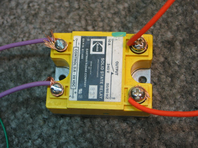
Using a SSR with higher output voltage and current ratings will work just fine. In fact use the highest current rating you can find. The typical ratings for the input is 3-32vdc with a must turn on at 3vdc and off below 1vdc. Input current is 10ms @12vdc. Outputs have ratings something like 24-280 vac @ 50 amps. Typical SSR like this is a Crydom CSW series
