The 555 Power Controler

If it plugs in, post it here.

Moderator: Site Moderator

FractionalDisMan
Novice
Posts: 31
Joined: Mon Sep 27, 2010 3:42 pm

The 555 Power Controler

Post by FractionalDisMan »

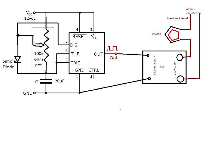
I've been reading about power control of the boiler heaters. I was a little uncomfortable about the high voltage going through the control circuitry using the triac system. For the high voltage side I wanted to use a SSR (solid state relay). I have used hundreds of these where I work with great results. The SSR gives cheep, high power switching with a low voltage control, and high to low voltage isolation greater than 2000 volts. Years ago I played with the 555 timer chip. With a little work I knew I could get the 555 to do what I want. Most of all I wanted to make it so anyone could attempt to make the power control.
Because of the large mass of the heater element and the liquid, I see no need for the speed of phase angle control in this type of heating application. Also phase angle firing produces a lot of electrical noise. The plan was to come up with a time base power control. This involves a set time frame that the power will turn on a percentage of this base time. For example, if I have a 2 second time base and wanted 50% power the power would turn on 100% for 1 second and off for one second. At 25% power setting, the power would turn on for 1/2 second and off for 1-1/2 seconds. I also wanted to get 0% to 100% control. I didn't know if I could get this but I was going to try.

The 555 timer IC output can drive up to 200ma so driving the SSR input (10ma @12v)directly from the chip output is possible. Also the 555 will work from 5v to 15v DC and the SSR has a must turn-on voltage of 3v so again a great fit. A good primer for the chip can be found at:

http://en.wikipedia.org/wiki/555_timer_IC" onclick="window.open(this.href);return false;" rel="nofollow

I modeled the circuit using LTSpice.

" LTspice®IV is a high performance Spice III simulator, schematic capture and waveform viewer with enhancements and models for easing the simulation of switching regulators. Our enhancements to Spice have made simulating switching regulators extremely fast compared to normal Spice simulators, allowing the user to view waveforms for most switching regulators in just a few minutes. Included in this download are Spice, Macro Models for 80% of Linear Technology's switching regulators, over 200 op amp models, as well as resistors, transistors and MOSFET models."

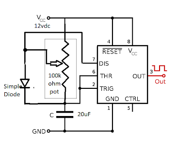
I started with the astable circuit below and modeled it into LTSpice.

Image

By changing the resistor values I could change the duty cycle (how long on to off) but could not get below 50% on. I added the diode across the one side of R2 and all worked. By keeping total resistance 100K ohms and changing R1 and R2 I could get any %on I wanted. The 20uF cap and the total resistance controls the time base. With the 100k ohm of resistors and 20uF gives a time base of 1.3 seconds, 10uf with the same pot will give a duty cycle of about .7 seconds. I then replaced R1 and R2 with a 100k ohm pot. The balance( wiper position) of the pot resistance controls percent on to off.
Image

I mocked up the circuit using a bread board and some spare parts. I placed a resistor with a LED on the output for testing. Below is the bread board mock up.


Image


The circuit worked perfect. I measured the output with a Fluke meter displaying the duty cycle ( % on to % off). . The range of the circuit will go from 0 to 100% and almost infinitely variable. I then hooked up a SSR and a lamp to confirm the output of the 555 could drive the SSR. Again perfect. I then went to the local electrical supply store and got a set of new parts and a small PC board. Below is the picture of the almost completed board.


Image

I was thinking I could mount board directly to the SSR input screws to reduce the size foot print. Drilled two holes for SSR input screws. Also I used two of the traces to get the signal to the SSR. Cut PC board smaller and mounted it.

Image

What do you know It works Great. To bad I cant solder worth shit! :roll:

So what does it cost to build? I got the PC board, cap, diode, 555, and pot for $11 USD. The SSR with shipping was $8 off Ebay. The 12vdc power supply was free, just find an old supply from 5vdc to 15vdc and don't worry about the power, the circuit doesn't draw much. To make the control feel good a 3-10 turn pot is real nice addition. A box, main power switch and some plugs and your done. A cheap easy to build power controler!
Parts List:
1 555 Timer ( note do not use low power version)
1 100k ohm linier pot ( liner, not log)
1 20uF electrolytic cap
1 simple diode
1 any 5-15vdc power supply (12vdc best)
1 SSR with 3-32VDC input and an output rating above what you would like to control
Misc plugs fuses etc.

Checking output with Fluke set to measure duty cycle ( %on to % off)! Meater at 50%. I can get any number from 0 to 100%
Image

Image

Please dont wire your test light like this! :shock:
Image

Some more notes: Back of SSR should be mounted using heat transfer compound to something to pull heat away. Please fuse AC line.

I can only get on line once and a while to answer questions. Please be patient, I will get back to most questions. This is a very cheap, safe, easy way to control the power to a heater. Please be safe.


Some Notes on SSRs:
A zero-cross SSR, when the control signal turns on or off the power side will wait until the AC wave crosses zero volts before switching off. In other words, the SSR will wait until there is no current flow before switching on or off. These SSR rated over 30 amps can be found on EBAY for $5-10. The SSR needed is a DC input zero cross with a output to exceed the voltage and power needed to control.
Image
Using a SSR with higher output voltage and current ratings will work just fine. In fact use the highest current rating you can find. The typical ratings for the input is 3-32vdc with a must turn on at 3vdc and off below 1vdc. Input current is 10ms @12vdc. Outputs have ratings something like 24-280 vac @ 50 amps. Typical SSR like this is a Crydom CSW series
MuleKicker
retired
Posts: 3111
Joined: Sun Jun 14, 2009 2:14 pm
Location: If I told you, I'd have to Kill You.

Re: The 555 Power Controler

Post by MuleKicker »

this is pulse width modulation. It works, but the AC output is not as smooth as phase angle control. I dont know why a noisy circuit matters with a heating element. I have never had a problem with it. Just because you can measure the dutycycle from 1 to 100%, doesnt meant the ac output is the same. You need a Burstfire, or random turn on relay to do that. Just like you said, the zerocross turns on and off when the ac wave crosses the 0 point. US current does this 60 times per second. and if your dutycycle turns on at 1 point, and the relay has to wait for the current to cross the 0 point, your either on a little to long or off a little too long. not a big deal, but when you look at how many times per second this happens, it is not as precise of control as phase angle control. I built a PWM controller, LWTCS runs it. It works good, but not as good as the Phase angle controllers. Havent had a complaint yet about noise, got lotsa folks here runnin them.
-Control Freak-
AKA MulekickerHDbrownNose
FractionalDisMan
Novice
Posts: 31
Joined: Mon Sep 27, 2010 3:42 pm

Re: The 555 Power Controler

Post by FractionalDisMan »

The noise of a phase angle makes my FM radio sound like an 747 at takeoff. I use a lot of phase angle here at work for very small (little mass)very fast acting heaters. For example I have a .005" nichrome wire wrapped in a .010" circle to ball the end of a .008" PP plastic fiber. I have to use PA (phase angle) . Full power would turn the wire white hot in milliseconds. I had to go to DC on one very fast system. This is the same reason PA is used to dim light bulbs. At the same time the 10kw heaters on a 6" plastic extruder can be left on for 10 minutes and because of the mass they are heating the temp barely changes. This is the same reason a electric wall heater just turns on full power and then off. There is no need to run a PA for this type of system. With a 5500w heater in 10 gallons of liquid (think lots of mass) I am not sure there would be a difference between PA at say 50% or a 1.2 second time base cycling at full power for .6 seconds and off for .6 seconds. A PA at 20% or a time base with the heater cycling on .24 seconds and then off for .96 seconds.

The US 60hz will cross the zero 120 times a second. The SSR will turn on or off at any one of these crosses. Once when the cycle goes from positive to negative and once going the other way. So if the time base was 1 second there would be 120 different power settings the can be achieved. But again, with the system we are controlling this is still way over kill. There would be a what I would call a rounding error. One on cycle might be 60 AC cycles and the next might be 61 AC cycles. But again who cares with this large system. Also, a PA is an on off control, just a very fast one. A part of the AC wave is let out 120 times a seconds with no rounding error.

Controlling a heater power output can be done many ways. PA (a very fast, very accelerate control), time based (easy to build,time base can be changed for different mass systems, and on off( large mass systems, or systems that can handle variations).

This is just another option for people wanting to run electric heaters. I myself am running propane. Thought I would contribute to the group.


Image
MuleKicker
retired
Posts: 3111
Joined: Sun Jun 14, 2009 2:14 pm
Location: If I told you, I'd have to Kill You.

Re: The 555 Power Controler

Post by MuleKicker »

The noise of a phase angle makes my FM radio sound like an 747 at takeoff.
Never had that experience with my phase angle controllers.
-Control Freak-
AKA MulekickerHDbrownNose
Manback
Swill Maker
Posts: 236
Joined: Sun Jul 18, 2010 11:33 pm

Re: The 555 Power Controler

Post by Manback »

Mod Edit: [ Inflamatory comments removed as they contributed nothing constructive to the topic. ]

P.S. FractionalDisMan cheers for this, I'm going to have a crack at building one :D
MuleKicker
retired
Posts: 3111
Joined: Sun Jun 14, 2009 2:14 pm
Location: If I told you, I'd have to Kill You.

Re: The 555 Power Controler

Post by MuleKicker »

I have tried PWM with a zero cross SSR, and it wasnt as precise as the phase angle controller. Nor, have I had the noise issues. True, i sell my controllers. But I have a complete tutorial for anyone who wants to do it themselves. I have answered countless PMs from people who want to and have built them themselves. I obviously have no problem with that.

Mod Edit: [ Inflamatory comments removed as they contributed nothing constructive to the topic. ]
-Control Freak-
AKA MulekickerHDbrownNose
FractionalDisMan
Novice
Posts: 31
Joined: Mon Sep 27, 2010 3:42 pm

Re: The 555 Power Controler

Post by FractionalDisMan »

Hey guy please lets keep this good. I dont know what was said but lets keep it positive. I have learned so much from this forum and am just giving back to the community with my knowledge. If any one would like to build these for people that either don't have the time or the knowledge, that is OK with me, just give me credit. It just helps out the community.

To all, MK gives a lot to this forum. Please respect him for this.

MB If you have any questions please post. If you have one so does some one else.

MK, I agree a zero cross will not work with a PWM. A PWM needs to turn the AC sign wave off in the middle of the wave which, as we know a zero cross cannot. I would be surprised if a zero cross would give any output with a PWM signal.
FractionalDisMan
Novice
Posts: 31
Joined: Mon Sep 27, 2010 3:42 pm

Re: The 555 Power Controler

Post by FractionalDisMan »

RC22, I did not even think I was being "dissed". I just saw this:

Mod Edit: [ Inflamatory comments removed as they contributed nothing constructive to the topic. ]

in two other posts. I didnt think it was about me. Sorry if my last post was taken that way. I can take all the "constructive criticism". With all the knowledge on the forum we can take some average idea and turn it into a great idea. Remember "It's all good"
MuleKicker
retired
Posts: 3111
Joined: Sun Jun 14, 2009 2:14 pm
Location: If I told you, I'd have to Kill You.

Re: The 555 Power Controler

Post by MuleKicker »

this control you have here is kinda like the SSRMAN build I have in the lounge. Although it is a PAC build. It mounts to the SSR and with the help of a 24v ac transformer to power and time the PAC module. the difference is your 555 timer isnt timed to the sign wave. I dont know how perfect the power control would be with it either, even with a burstfire relay.(which is what the SSRMAN calls for) I understand what you think when you say we dont need to be that precise. But, when a guy needs to controll a still and be competitive with the control of gas, phase angle is the way to go. It is the fine control of your rig that gives you the edge. That fine control can be key.
Trust me, i cant sit and still all day without my radio on, and i have never had an interference from my control. If anyone else has, let me know.... Im currious.
As for how smooth this control is, I think you could build one and install an amp meter to it. if it bounces, or does not go up smoothly with the dial, we will know... Right?
FractionalDisman wrote: I would be surprised if a zero cross would give any output with a PWM signal.
Yes, it does give output, just not perfectly smooth/accurate. I have experimented with this. I built an arduino controller so i could tweek the PWM on time/off time, and total cycle times. I couldnt get it perfect. I tried zerocross, and burstfire relays. The best results came when i took a total cycle time in a multiple of 16.6. cause 1 ac cycle took 16.6 milliseconds. I took 166. I would turn on for 16.6, off for 149.4, (for 10% duty cycle).... you get the point. so it was good, but after i got the SSRMAN going i gave up on PWM. Then Pamuli found the PSR-25 module, which did the same thing, with fewer parts, cheaper.
No disrespect was meant to FDM earlier, and i am sorry for "muddy-ing up" his topic. Cheers.

FDM, build it. (looks like your already up on that :D ) Get some hard results from a run. Im currious what that amp meter will do. You are correct, this is how we get new breakthroughs. Gotta go through the R&D. 8)
-Control Freak-
AKA MulekickerHDbrownNose
condensificator
Rumrunner
Posts: 653
Joined: Wed Jul 28, 2010 7:34 pm

Re: The 555 Power Controler

Post by condensificator »

just FYI, i read this thread before it was edited.


MK never tried to sell me sh*t, but i went looking for his wares after reading through a ton of stuff about heat control...so i asked him to build me one. he was nothing but polite, and after i got his controller, it changed my whole game.

i have never heard so much as a whisper from the unit, not from cold start to long run. i am able to get running from cold start in less than 1/2hour or blow tails out the ass at full heat, or with a light touch of the dial, go from full stream to pencil lead stream to drops...i am VERY happy with the unit that i got from MK. then, when he put up the ampmeter in his thread, i started looking for one to install on mine on eaby...hours later, without me even asking about it, he sent me a message offering to put on one mine for a charge less than what i found them for online!

i'm a pretty handy guy...i do basic household wiring, problemsolving and troubleshooting stuff that breaks, but i know what my strengths are and they most definitely are not electrical/electronic stuff. i could have made one myself, but i could not be happier with my MK5500W purchase......so, back on topic...this 555 controller looks AWESOME! might have to try one of them myself for the next project. thank you very much for sharing.


yes, indeed, many ways to skin a cat. let's all just get around the fire and compare pelts.
Manback
Swill Maker
Posts: 236
Joined: Sun Jul 18, 2010 11:33 pm

Re: The 555 Power Controler

Post by Manback »

condensificator wrote:just FYI, i read this thread before it was edited.


MK never tried to sell me sh*t, but i went looking for his wares after reading through a ton of stuff about heat control...so i asked him to build me one. he was nothing but polite, and after i got his controller, it changed my whole game.

i have never heard so much as a whisper from the unit, not from cold start to long run. i am able to get running from cold start in less than 1/2hour or blow tails out the ass at full heat, or with a light touch of the dial, go from full stream to pencil lead stream to drops...i am VERY happy with the unit that i got from MK. then, when he put up the ampmeter in his thread, i started looking for one to install on mine on eaby...hours later, without me even asking about it, he sent me a message offering to put on one mine for a charge less than what i found them for online!

i'm a pretty handy guy...i do basic household wiring, problemsolving and troubleshooting stuff that breaks, but i know what my strengths are and they most definitely are not electrical/electronic stuff. i could have made one myself, but i could not be happier with my MK5500W purchase...i will be referring all of the people that i get talked into partnering in crime.


yes, indeed, many ways to skin a cat. let's all just get around the fire and compare pelts.
I don't have one condensificator. But I'm more than willing to believe it, they are tidy as little units and I even tried to buy one myself - it may well be (I suspect it is) that the MK5500W is by far the best unit for $$ around. But there's no need to go bagging on the other ways of skinning a cat - a little research would give any reader the info they require to decide which unit they prefer to build.

Then again I was in a bad mood this morning and was probably a cock about it.

:oops:
condensificator
Rumrunner
Posts: 653
Joined: Wed Jul 28, 2010 7:34 pm

Re: The 555 Power Controler

Post by condensificator »

i don't think he was "bagging," just having a constructive discussion about something that they both have knowledge about.
MuleKicker
retired
Posts: 3111
Joined: Sun Jun 14, 2009 2:14 pm
Location: If I told you, I'd have to Kill You.

Re: The 555 Power Controler

Post by MuleKicker »

thanks c. this topic aint about my controllers guys. unless you want to contribut to the noise issue. lets let FDM have his topic back. :D
-Control Freak-
AKA MulekickerHDbrownNose
User avatar
LWTCS
Site Mod
Posts: 13025
Joined: Mon Jan 26, 2009 6:04 pm
Location: Treasure Coast

Re: The 555 Power Controler

Post by LWTCS »

Would it be helpful for one to use the 3/8 vs.1/2 worm analogy?
Be a no brainer then wouldn't it?


Most of us want an equal to,,or better bit of control.
Trample the injured and hurdle the dead.
rad14701
retired
Posts: 20865
Joined: Wed Dec 19, 2007 4:46 pm
Location: New York, USA

Re: The 555 Power Controler

Post by rad14701 »

LWTCS wrote:Would it be helpful for one to use the 3/8 vs.1/2 worm analogy?
You've lost me with the worm talk, Larry... :econfused:

I don't think you've been sippin' because you've got your spellin' and punctuatin' under control... :P
FractionalDisMan
Novice
Posts: 31
Joined: Mon Sep 27, 2010 3:42 pm

Re: The 555 Power Controler

Post by FractionalDisMan »

Doin a run as we speak so take this as you will (sipping), and yes with gas. I did this controller not to step on any ones toes. I wanted to give back to yaall because I got so much from you.

My last comments on PA

Phase angle (PA) turns on and off just like any other controller unless the voltage is converted to DC. If a PA is running at 25% then the power turns on at zero volts and ramps up for .0021 seconds and then immediately goes to zero volts for .0063 seconds . This is then repeated. over and over. IT IS going on and off. Light bulbs go on and off 120 (60hz) times a second. We cant see it. Your TV is flashing 30 or 60 (has to do with lacing)times a second. We cant see it. If we have a heater heating 25 L of water and it is turning on and off every .5 seconds will the process notice? Another example, I love to use water as a comparison to electric. We have two hoses at full open will put out 20 L/min one has a valve that can regulate flow (PA) the other is only on and off (Time base). The first one we adjust to 50% flow, 10L/min. The other we have it turn on full for .5 seconds and off for .5 seconds over and over. At the end of one second, one minute, one hour, which one had the higher output? Correct! They were both the same.

Another thought. on time base. What if the TB (time base) controler could do one AC cycle on and one off for a 50% power? On and off 60 times a second (.016 sec). What about 2 cycles on and two off? Still at 50% (.033 sec). Three on(.05s), three off(.05s)....think the 25L liquid system would react any different yet?.................36 on 36 off (.6 sec each) Oh, why yes a 1.2 second time based controller! But wait dont order yet. What about, say, lets get crazy, 120 cycles each on and 120 off still only 2 second on and 2 off. Will the 25L of water see this difference?

Must have another sip.

This controller is cheep to make. Safe. Will give 0 to 100% power control with almost infinite power settings. If anyone has any questions about the controller please post. No more about PWM and Time Base unless someone has a good question.

Got to go play poker. Seee ya
MuleKicker
retired
Posts: 3111
Joined: Sun Jun 14, 2009 2:14 pm
Location: If I told you, I'd have to Kill You.

Re: The 555 Power Controler

Post by MuleKicker »

PWM works great with DC, AC is a little tricky-er cause of the "ups and downs" your water analogy is great, but the water pressure is constant, not fluctuating up and down 120psi and back to 0. if you turned that water on and off every half second for so long and it happend to be when the water pressure was on the bottom half of the pressure cycle, you would not have the same output. I am no electrical engineer, or electrician. So correct me if im wrong. Im not saying your controller wont work. I just want nuts on power control.. Just like gas can offer. And dont think your stepping on anyones toes. Although, Sometimes toes need to be stepped on :D
-Control Freak-
AKA MulekickerHDbrownNose
User avatar
LWTCS
Site Mod
Posts: 13025
Joined: Mon Jan 26, 2009 6:04 pm
Location: Treasure Coast

Re: The 555 Power Controler

Post by LWTCS »

No toes stepped on by the OP at all.
Great post,great bit of info.

Things have moved forward however

No matter
Thanks for posting
Trample the injured and hurdle the dead.
Thorn_veritas
Swill Maker
Posts: 188
Joined: Sat Oct 03, 2009 7:59 am

Re: The 555 Power Controler

Post by Thorn_veritas »

My head hurts :esad: :esad: :esad:
monkymate
Novice
Posts: 14
Joined: Tue Nov 02, 2010 1:56 pm

Re: The 555 Power Controler

Post by monkymate »

I am building one of these controllers. Here are my reasons and some particulars of my build.

-Parts (except the SSR go to EBay for that) are available at Radio Shack and Home Depot and the cost was very reasonable. It looks like I will have about $70=$80 total in the whole controller, box, cords, heater element and all. I will give a complete parts list and costs when done with lots of pictures.

-I have a 30 amp DPST switch to shut off all main power, also adding a SPST 30 amp switch to bypass the SSR and the controller for intial heatup and stripping. That way the heat sink for the SSR will not be used during those times when I need full power.

-I have run gas, induction hot plate (Burton 1800 watt) for 10 years and now have the keg with 4500 watt heater for stilling. The gas is good but at what risk? We are working with a highly flammable gas/liquid. With beer and mash I do not have the flammable problem so gas is great. If you run gas where you should (well ventilated space then there may be breezes and things that will change the heat transfer of the gas heat to the pot. Also as the bottle loses volume, temp changes the gas can change, and regulators are not perfect either. There is no perfect power source. Just different ways to skin a cat. The induction plate worked well for me on my 1st 2 batches of 5 gallons of wash but the heatup time was a little slow and I was afraid of the weight on the glass top. No worries about flame or spark though and the control was awesome.

-I looked all over the board and saw the SSRMAN option, the PSR-25 option, the dimmer switch Triac/diac setups and the 555 Timer/SSR option. What I saw out of most of it was everyone was able to get each of those options to work and was happy with what they made using them. With the fractional columns making high proof neutrals it looks like any of these will work. Some are smooth and elegant and others are crude but effective. But they all seem to work.

I have all the parts now except the SSR (still in route). I will document the build and give a good account of how it works.

Monkymate
monkymate
Novice
Posts: 14
Joined: Tue Nov 02, 2010 1:56 pm

Re: The 555 Power Controler

Post by monkymate »

Well the controller is built and works great. My meter had a % function and the SSR has a led on the input side. It ramps up and down fine. Still waiting on the heat sink to finish it. I have to say thanks to FractionalDisMan for his plans for this. NOTE: I have not run this yet. I will do some testing with water and my Pot Still Stripping head to test how well I can control with it and report on that when I finish it.

Costs:
240V 10/2 6' Dryer Cord at Home Depot = $15
240V 12/2 9' Air Conditioner Cord Home Depot =$15 (Cut the cord and used male end on boiler and female coming out of controller.)
6x6x4 Plastic Box Home Depot = $7
30 Amp DPST Switch Home Depot = $15
30 Amp SPST Switch Home Depot = $12
SSR 600V 25 Amp Zero Cross Relay Ebay = $18 with priority shipping
Heat Sink for SSR Ebay = $10 with shipping
Parts at Radio Shack for controller = $12 (Everything for this controller board can be bought there.)
Stainless Keg for Boiler - Craigslist = $25
4500 Watt 240V Low Density Heater Element Home Depot = $18
3/4" Ball Valve for Drain and Misc. copper fittings (Parts Bin) = Free
Time to make something that gives me much enjoyment and brush up on some electrical/electronics knowledge = PRICELESS!

So for about $147 I built a 15.5 gallon 4500watt controllable electric boiler that should last a long time.

It also met several criteria for my build.
-All in one control box
-Switch that turns off whole unit
-Switch to bypass the controller for full power during boil and stripping etc. (Saves life on the SSR and doesn't heat up the heat Sink when in this bypass full power mode.)
-Modular I.E. controller is limited to the cords and Box. It is not attached to the boiler.

Monkymate
monkymate
Novice
Posts: 14
Joined: Tue Nov 02, 2010 1:56 pm

Re: The 555 Power Controler

Post by monkymate »

Status Update and Performance Review of 555 Timer / 4500 Watt 240V Controller

Finished the Build today and ran it with water and used my Pot Still Head. System worked beautifully and the stream was instantly controllable using the controller. Stream size could be taken from drops to a large pencil lead stream with a twist of the dial and back down again. No surging or inconsistent heating was evident. Did this several times both slowly and fast to verify it works. The volume of the Keg (15 gallons filled with 10 gallons water) and the cycle time of timer (never off more than a second) made sure that the boil was controllable and steady.

Tested the unit at full power and allowed the heat sink to heat up. It was still touchable with a hand and didn't burn me. Seemed to steady out after about 30 minutes.

In bypass mode the heat sink stayed cool to the touch.

The Radio Shack Linear Pot I used has a dead area at the 0% and a ON area at the 100% area that are not linear with the rest of the scale. Other than those spots the rest of it was linear and predictable. I hooked my meter to it and could reproduce any % I wanted after I marked them on the box. I just put 0-10 markings for 10% between marks. My Pot has a range of 7/8 of a revolution. I wanted markings on the box and did not want to go with a 3 turn pot or something that went greater than 1 full turn.

Now for the bad. I would not recommend you build this unless you have some experience with making circuits on a circuit board. It is a little (maybe $25-$50) cheaper BUT I would have saved myself allot of hassle by going the PSR-25 route. With the 2 cords, ON/OFF Switch, Bypass Switch, 12VDC Transformer, SSR, and control circuit I BARELY got it all to fit in a 6x6x4 Plastic Box. You have to be careful since you have a low voltage DC side and a High Voltage AC side to this. Might be better for the control circuit to be in a different box. I made sure everything was insulated well and grounded all of the components. I wrap each switch with tape after connecting the wires to it also. The only connections not insulated are on the SSR. You could get a cover for this to keep anything from touching the terminals if needed.

I did not take pictures of the build. If you can follow a circuit and build a board then what I have described and what FractionalDisMan has put up should be plenty.

Monkymate
FractionalDisMan
Novice
Posts: 31
Joined: Mon Sep 27, 2010 3:42 pm

Re: The 555 Power Controler

Post by FractionalDisMan »

Monkeymate, Glad it works for you as well as it worked for me. Did you use a pc board to mount the low voltage control parts? And did you mount the pc board to the SSR? This part of the package is very small. The low voltage is isolated (4000 volts) from the high voltage by the SSR so no problem mounting the pc board there. To save even more room a small transformer with a bridge rectifier and a capacitor mounted on the pc board. If the SSR is rated for the current of the heater (I rate them to 150% over) should have no problem running at 100% power. Also using a SSR with a very large power rating will not change anything and the cost of the higher power SSRs does not seem to be much difference. Also the SSR switches at the zero voltage cross, the switching is where most heat comes from. So I dont think the full power switch is needed just an On-Off switch. I would think it would all fit very comfortably in a single gang box.
.

Any who... Glad it worked out for you.
rad14701
retired
Posts: 20865
Joined: Wed Dec 19, 2007 4:46 pm
Location: New York, USA

Re: The 555 Power Controler

Post by rad14701 »

I have read through several SSR data sheets and instructional manuals and the common consensus has been that as follows...

For 120V mains input a 200V SSR is suggested... If it will be operating in an RFI or EMI noisy environment then a 400V SSR is suggested...

For 240V main input a 400V SSR is suggested... If it will be operating in an RFI or EMI noisy environment then a 600V SSR is suggested...

I have purchased parts and have constructed one 555 PWM of an alternate design from the one originally posted which uses two diodes... I have enough parts to build one based on the common design FractionalDisMan posted... I am planning on using the PWM in conjunction with an opto-coupler of the opto-diac triac triggering design... Any opto-coupler used needs to be of the non-zero crossing category for resistive loads...
mrtom
Novice
Posts: 5
Joined: Sat Apr 30, 2011 5:48 pm

Re: The 555 Power Controler

Post by mrtom »

I have been successfully using a similar setup to this for some time with a duty cycle controller firing a 40A SSR. My circuit uses a 10 second cycle time and is variable from 0 to 100% on time and is heating a 15 gallon beer keg sized boiler. Your kitchen stove burners work in a similar manner, which is what gave me the inspiration to try this method. In my estimation, all this talk of accuracy and phase angle switching is completely unneccessary, and is quite frankly overkill for what we are talking about doing here. All we want to do is control the amount of heat going into a relatively large mass of fluid. This is a simple and practical solution to control an element without costly electronics or too much electronic experience.
MuleKicker
retired
Posts: 3111
Joined: Sun Jun 14, 2009 2:14 pm
Location: If I told you, I'd have to Kill You.

Re: The 555 Power Controler

Post by MuleKicker »

10 second cycle? That seems a little to wide. So, if your running at 10%, your element is on for 1 second and off for 9? 25% = on for 2.5 sec, off for 7.5? That is deffinately going to cause surging. Phase angle may be more precise than we truly need, but it is effective.
-Control Freak-
AKA MulekickerHDbrownNose
gr8brewer
Novice
Posts: 49
Joined: Tue Feb 22, 2011 6:39 am

Re: The 555 Power Controler

Post by gr8brewer »

rockchucker22 wrote:
MuleKicker wrote:I have tried PWM with a zero cross SSR, and it wasnt as precise as the phase angle controller. Nor, have I had the noise issues. True, i sell my controllers. But I have a complete tutorial for anyone who wants to do it themselves. I have answered countless PMs from people who want to and have built them themselves. I obviously have no problem with that.

Mod Edit: [ Inflamatory comments removed as they contributed nothing constructive to the topic. ]
Very true Mule kicker has been so helpfull. I'm a mindless idiot and he has put up with my pms and tried to help me.....free no charge :mrgreen:
Yup his tutorial helped me build mt controller.
rad14701
retired
Posts: 20865
Joined: Wed Dec 19, 2007 4:46 pm
Location: New York, USA

Re: The 555 Power Controler

Post by rad14701 »

Phase control is also cheaper and easier to build, especially for those with relatively little experience in working with electronics... I've played with several 555 based designs and I keep going back to phase angle controllers...

I was also going to reply to the broad timing of the 555 cycles last night but life got in the way... At that cycling rate you might as well use an electric range element controller...
mrtom
Novice
Posts: 5
Joined: Sat Apr 30, 2011 5:48 pm

Re: The 555 Power Controler

Post by mrtom »

MuleKicker wrote:10 second cycle? That seems a little to wide. So, if your running at 10%, your element is on for 1 second and off for 9? 25% = on for 2.5 sec, off for 7.5? That is deffinately going to cause surging. Phase angle may be more precise than we truly need, but it is effective.

I just rechecked my timing with the resistors/caps I used when building my board and it is actually a 1 second time window for the cycle. I had 10 in my head for some reason, but I built the thing some time ago. I just began digging my rig out of storage and want to get it running again. I have not had time to run it in a couple of years and I am running out of spirit.

Since I have last viewed this site there seems to be a lot of new stuff to take in. This whole flute business has me very interested. I had read a lot about plate columns, but did not think it was doable for a small hobby rig. When I built my last unit, I tig welded a 3" triclover to the top of a beer keg, added a 1" threaded bung hole for a heater and one for a drain. I wanted to leave it wide open for future improvements and the ability to heat with gas as well. My previous boiler was gas only and with a 4 ft column was still visible over the fence and looked rather suspiciously like a still. I'd like to be able to cook inside as well.

My 3" stainless column has triclovers on each end to allow for different setups. I like the nixon-stone head, but also have built a VM head which is almost complete. I am looking enviously at the flute design and thinking how easily this could go onto my boiler for whiskys and brandys. I like all of the copper! I usually put a copper scrubber in my column to clean up the vapours and always end up with a fantastic neutral spirit.

I think I am going to have to build one! There is sure a lot of reading on the topic. Cheers!
User avatar
LWTCS
Site Mod
Posts: 13025
Joined: Mon Jan 26, 2009 6:04 pm
Location: Treasure Coast

Re: The 555 Power Controler

Post by LWTCS »

Its all the rage now mrtom. And for good reason.

Recon it was one (or more)of the eggheads that posted it couldn't be done. Too much scribbling with pen and pad and not enough real time R&D.......No offense intended.

Plenty of testimonials from column operators kickin about too.
mrtom wrote:I have not had time to run it in a couple of years and I am running out of spirit.


Jumpin Jesus on a pogo stick! You must have been well stocked?
Trample the injured and hurdle the dead.
Post Reply